Data collection and processing apparatus with Anti-theft function, system using the same, and data collection and processing method thereof

Active Publication Date: 2017-08-03
QUASION +1
2 Cites 6 Cited by

AI-Extracted Technical Summary

Problems solved by technology

However, such methods are disadvantageous for the following reasons.
1. Images acquired by surveillance cameras have to be analyzed by human, often resulting in incomplete statistical observation or missing data.
2. On-site human observation affects user behaviors, reducing the accuracy of statistical analysis.
3. Camera surveillance or human on-site observation cost delay in discovery ...

Benefits of technology

[0026]Furthermore, the present invention is also capable of receiving alert signals or status and operational information from any data collection and processing apparatus, and prov...

Abstract

A data collection and processing apparatus with anti-theft function is provided. The data collection and processing apparatus is configured for collecting and processing relevant information regarding at least one targeted object, wherein the relevant information comprises information indicating whether the targeted object is under a normal status. The data collection and processing apparatus is also configured for processing the relevant information and performing an alarm when detecting that the targeted object is not under the normal status. A data collection and processing system with anti-theft function using the apparatus and a data collection and processing method thereof are also provided.

Application Domain

Burglar alarm by hand-portable articles removalBurglar alarm by disturbance/breaking stretched cords/wires

Technology Topic

Anti theftCollections data +3

Image

  • Data collection and processing apparatus with Anti-theft function, system using the same, and data collection and processing method thereof
  • Data collection and processing apparatus with Anti-theft function, system using the same, and data collection and processing method thereof
  • Data collection and processing apparatus with Anti-theft function, system using the same, and data collection and processing method thereof

Examples

  • Experimental program(1)

Example

[0038]The present invention will now be described more specifically with reference to the following embodiments. It is to be noted that the following descriptions of preferred embodiments of this invention are presented herein for purpose of illustration and description only. It is not intended to be exhaustive or to be limited to the precise form disclosed.
[0039]Based on the disadvantages of existing anti-theft devices, the present invention provides an anti-theft data collection and processing apparatus, and an anti-theft data collection and processing system of and a method for such apparatus.
[0040]The anti-theft data collection and processing apparatus of the present invention is capable of detecting if at least one targeted object is under a normal status and performing alarms (for example, releasing alarm signals) when detecting that the at least one targeted object is not under the normal status, therefore achieving anti-theft effects. In other words, the targeted object is the item protected by the anti-theft data collection and processing apparatus.
[0041]In the present invention, “normal status” refers to the condition under which the targeted object is being protected. Such condition may be, for example, the targeted object being at a certain location or located within a certain area, or not being illegally operated. It is to be understood that the “normal status” may be defined by the users according to the practical environments, and is not limited to any specific condition in the present invention.
[0042]In addition to collecting and processing information regarding whether the targeted object is under the “normal status,” the data collection and processing apparatus of the present invention is capable of collecting various (relevant) information regarding the targeted object, such as other status information and/or operational information of the object, environmental information regarding the environment in which the object is located, and user information regarding the owner or user of the object. The “status information” of the object reflects all attributes information of the status of the object, including information indicating whether the object is under the “normal status.” The “operational information” refers to information generated according to operations of the object by the user, including duration of operation and content of operation. The “environmental information” refers to the information regarding the environment in which the object is located, such as temperature, humidity, and intensities of light, electricity or magnetic field, as well as video or images of the environment (when surveillance cameras or probes are adopted). The user information regarding the owner or user of the object includes, for example, gender and age of the owner or user of the object.
[0043]The targeted object according to the present invention may be a cell phone, a tablet computer, a laptop, a digital camera, or other interactive electronic device. For example, when the targeted object is an electronic device and is electrically connected to the data collection and processing apparatus, the status information may include the status of connection between the data collection and processing apparatus and the electronic device, the operational information may include information regarding the interactive operations between the user and the object, the environmental information may include surveillance images, temperature, humidity and light intensity of the spatial area in which the electronic device is located, and the user information may include gender and age of the user of the electronic device.
[0044]The data collection and processing apparatus of the present invention may be associated with one or a plurality of targeted objects. That is, a data collection and processing apparatus of the present invention may collect and process relevant information of at least one targeted object.
[0045]In other words, the data collection and processing apparatus of the present invention may detect relevant information of at least one targeted object, such as information indicating whether the targeted object is under a “normal status.”
[0046]The data collection and processing apparatus of the present invention may be an independent functional device, or be integrated into other electronic device or the targeted object. For example, the apparatus may be implemented by one or more components in a smartphone having all of the functional modules in accordance with the present invention. The functional modules may be constituted by hardware components or be implemented by common data processing device (for example, a CPU) that is capable of executing relevant programs or applications and having data processing capability.
[0047]The present invention also provides a data collection and processing method. According to the method, relevant information of at least one targeted object is collected, and status of the targeted object is determined. An alarm would be performed when the targeted object is determined to be not under the normal status. The collected relevant information may also be processed for performing interactive operations accordingly.
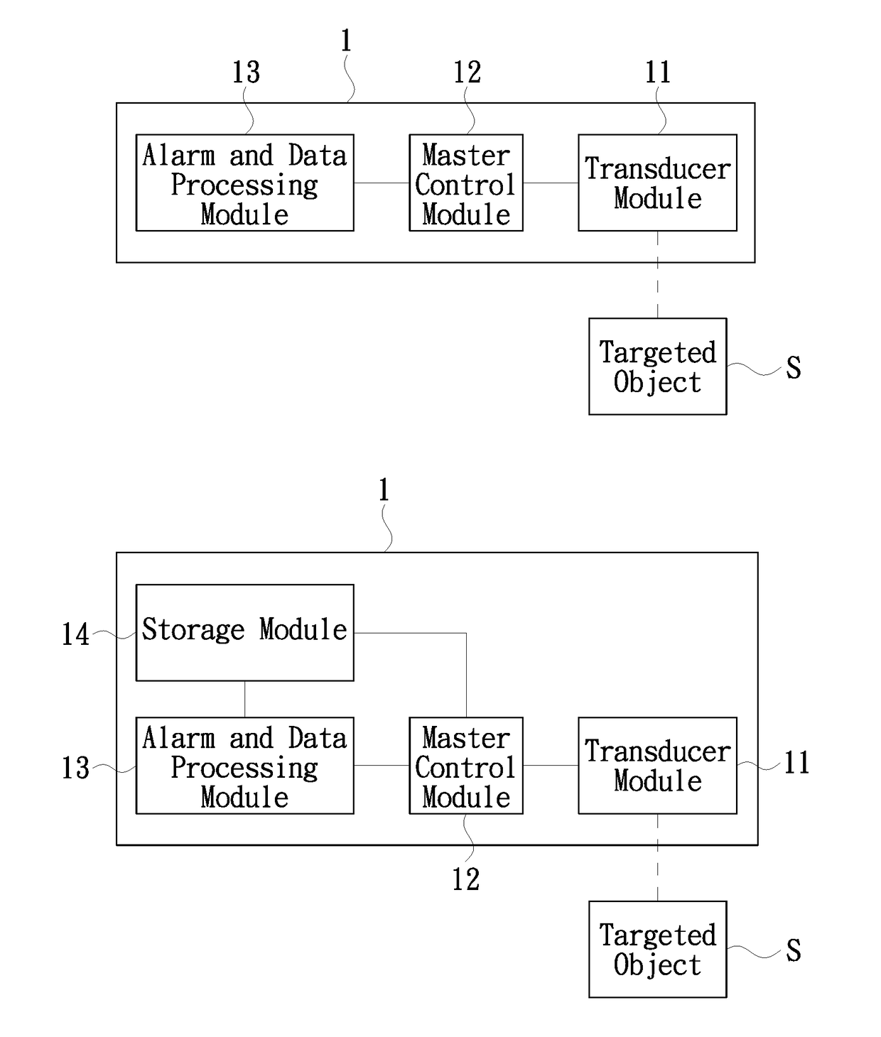
[0048]Referring now to FIG. 1A, which illustrates the configuration of an anti-theft data collection and processing apparatus according to an embodiment of the present invention. As shown in FIG. 1A, the anti-theft data collection and processing apparatus of the present invention includes a transducer module 11, a master control module 12 and an alarm and data processing module 13.
[0049]The transducer module 11 is configured to collect relevant information of a targeted object S. The information may contain status information, which may include the status of connection between the targeted object S and the data collection and processing apparatus 1 and positional status of the targeted object S, and operational information, which may include interaction between the user and the targeted object S and user information. The transducer module 11 would then transmit the relevant information to the master control module 12. The relevant information may be in any format, such as acoustic, light, electrical, mechanical, or scent. The transducer module 11 may be any type of transducers, including mechanical switch, MEMS transducer, Hall effect transducer switch, infrared transducer, proximity transducer, and camera transducer, and may collect data and images.
[0050]For example, if the transducer module 11 is a mechanical switch connecting to a targeted object, the master control module 12 would be notified once the status of the mechanical switch is altered. If the transducer module 11 is a Hall effect transducer switch, the master control module 12 would be notified once the status of the Hall switch is altered. If the transducer module 11 is a transducer capable of detecting the presence of the targeted object within a certain area, such as an infrared transducer, a MEMS transducer, a proximity transducer or a camera transducer, the positional status and other information of the targeted object would be reported to the master control module 12. Furthermore, when the user interacts with the targeted object, the transducer module 11 may also record the operational, environmental and user information of the interaction, such as age, gender and facial expression of the user, image of the space in which the targeted object is located, and duration and steps of the user operation, which are then sent to the master control module 12.
[0051]The master control module 12 is configured to determine if the targeted object is under a “normal status” and to transmit an alert signal to the alarm and data processing module 13 when the targeted object is determined to be not under the “normal status.” The master control module 12 is also configured to transmit relevant information received from the transducer module 11, including user information and operational information regarding interactions between the user and the targeted object, to the alarm and data processing module 13. The master control module 12 may be implemented by a microprocessor or other component with digital processing capability, such as a FPGA or DSP.
[0052]The alarm and data processing module 13 is configured to process the alert signal sent from the master control module 12 and perform an alarm, such as activating an alarm annunciator to set off an alarm. The alert and data processing module 13 is also configured to process relevant information received from the master control module 12 and perform interactive operations accordingly. The interactive operations may be performed in acoustic, light, electrical, scent, or mechanical formats. The alarm and data processing module 13 may be implemented by an independent processor coupled with components with related functions, and may share the processor with the master control module 12.
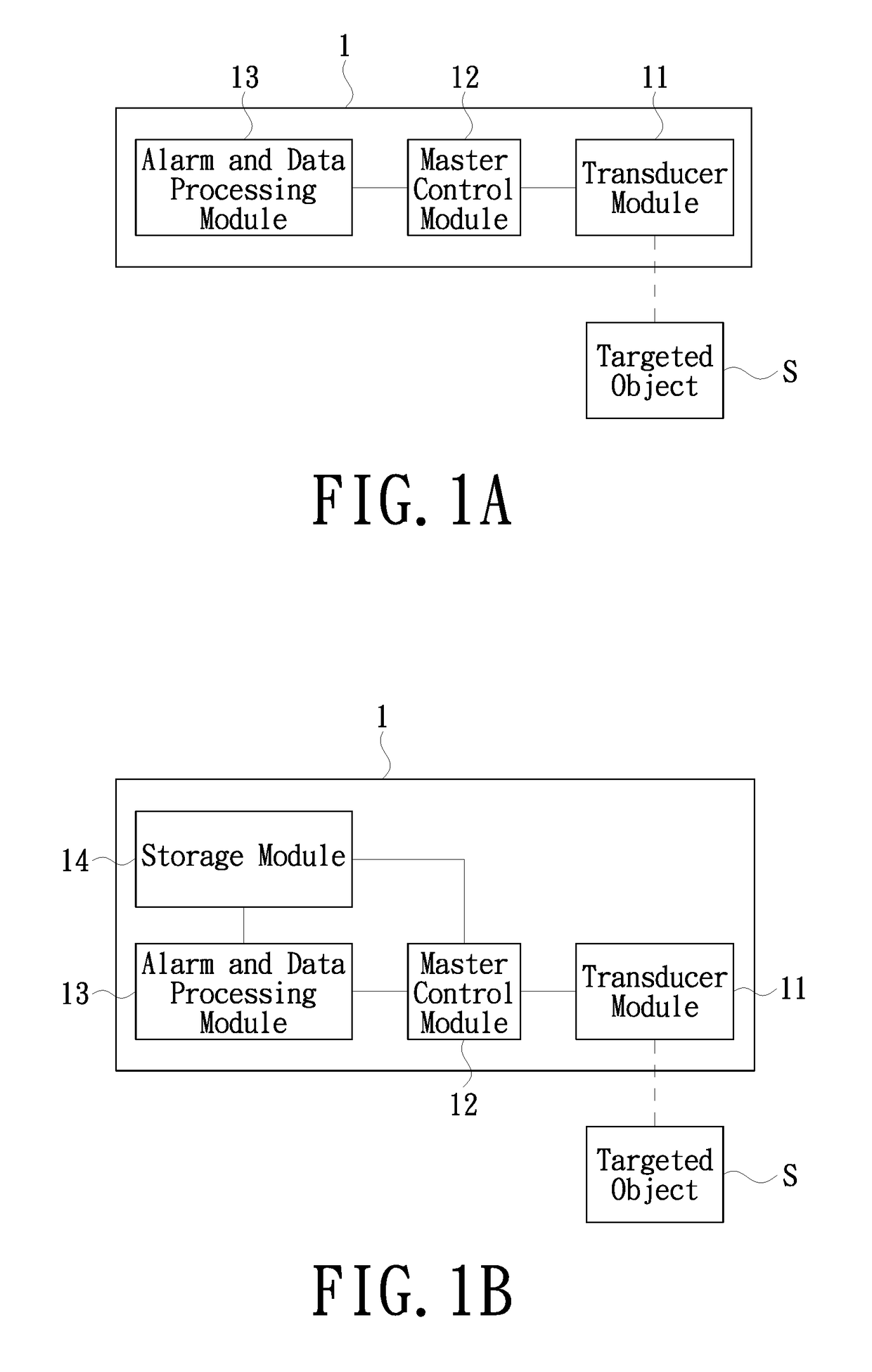
[0053]Referring now to FIG. 1B, which illustrates the configuration of an anti-theft data collection and processing apparatus according to another embodiment of the present invention. Different from the configuration illustrated in FIG. 1A, the data collection and processing apparatus of the present embodiment further includes a storage module 14. The storage module 14 is configured to store the relevant information and data generated by the master control module 12 or generated upon processing of the relevant information by the alarm and data processing module 13. The storage module 14 may be implemented by any storage device with read and write function, such as NAND Flash Memory, mini-SD, T-Flash, RS-MMC.
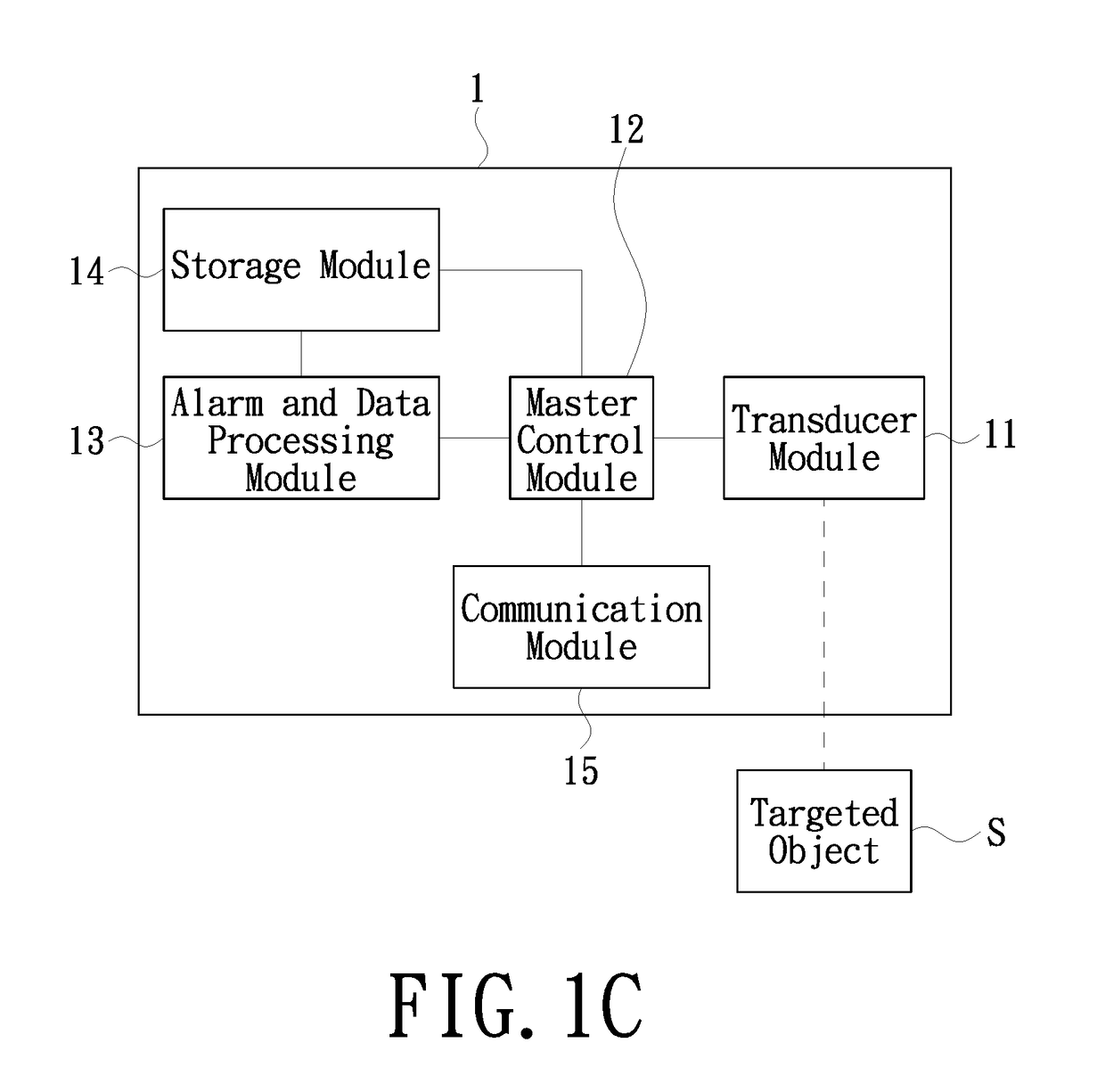
[0054]Referring now FIG. 1C, which illustrates the configuration of an anti-theft data collection and processing apparatus according to yet another embodiment of the present invention. Different from the configuration illustrated in FIG. 1B, the data collection and processing apparatus of the present embodiment further includes a communication module 15.
[0055]The communication module 15 is configured to transmit the alert signal received from the master control module 12 to an external device that is capable of processing the alert signal, and to transmit information collected by the transducer module 11 regarding the targeted object to an external device that is capable of processing the relevant information. The communication module 15 may or may not be connected to the Internet, and data communication thereof may be wired or wireless by utilizing, for example, near filed communication (NFC), Bluetooth, WiFi, 2G/3G/LTE mobile network or frequency modulation (FM). More specifically, data exchange may be performed without Internet connection by using NFC, Bluetooth, infrared or WiFi, or with Internet connection by using 2G/3G/LTE or other Internet connection means. The present invention is not limited to the aforementioned data communication methods.
[0056]Referring now to FIGS. 2A and 2B, each illustrating an anti-theft data collection and processing system of the present invention.
[0057]As shown in FIG. 2A, the system includes at least one data collection and processing apparatus 1 and an alarm and data processing apparatus 2. The data collection and processing apparatuses 1 and the alarm and data processing apparatus 2 are communicated by wired or wireless connection.
[0058]The data collection and processing apparatuses 1 are configured to collect relevant information of at least one targeted object S, and transmit the collected relevant information to the alarm and data processing apparatus 2. The relevant information includes information indicating whether the targeted object S is under a “normal status”. An alarm would be performed when the alarm and data processing apparatus 2 processes the relevant information and determines that the targeted object S is not under a normal status.
[0059]The data collection and processing apparatuses 1 of the system in the present embodiment are similar to the data collection and processing apparatus 1 of the previous embodiments. The difference is that the data collection and processing apparatuses of the present embodiment do not include the alarm and data processing module 14. However, the data collection and processing apparatuses each has a communication module 15.
[0060]Each transducer module 11 of the data collection and processing apparatuses 1 may detect the relevant information of at least one object S.
[0061]The communication modules 15 are configured to transmit alert signals received from the master control module 12 to the alarm and data processing apparatus 2, and to transmit relevant information collected by the transducer module 11 regarding the targeted object S to the alarm and data processing apparatus 2. The communication modules 15 may or may not be connected to the Internet, and data communication thereof may be wired or wireless by utilizing, for example, NFC, Bluetooth, WiFi, 2G/3G/LTE or FM. More specifically, data exchange may be performed without Internet connection by using NFC, Bluetooth, infrared or WiFi, or with Internet connection by using 2G/3G/LTE or other Internet connection means. The present invention is not limited to the aforementioned data communication methods.
[0062]The alarm and data processing apparatus 2 is configured to receive alert signals or status and operational information from any of the data collection and processing apparatus 1, and perform alarms according to the alert signals or interactive operations according to the status and operational information.
[0063]Additionally, each of the data collection and processing apparatuses 1 further includes an alarm and data processing module 13 (not shown). The alarm and data processing module 13 is configured to process the alert signals received from the master control module 12 and perform alarms accordingly, and to process relevant information sent from the master control module 12 or perform interactive operations accordingly. The master control module 12 is also configured to determine if sending the alert signals and the relevant information to the alarm and data processing module 13 or to the alarm and data processing apparatus 2.
[0064]Each of the data collection and processing apparatuses 1 may further includes a storage module 14 for storing relevant information and data generated by the master control module 12 or generated upon processing of the relevant information by the alarm and data processing module 13.
[0065]Referring now to FIG. 2B. Similar to the system shown in FIG. 2A, the anti-theft data collection and processing system in the present embodiment as illustrated in FIG. 2B includes at least one data collection and processing apparatus 1, each collecting and processing relevant information of a targeted object S.
[0066]However, different from the embodiment shown in FIG. 2A, the data collection and processing apparatuses 1 of the present embodiment employ the data collection and processing apparatus shown in FIG. 1C. In other words, in addition to the transducer module 11, the master control module 12 and the communication module 15 as in the data collection and processing apparatus 1 illustrated in FIG. 2A, the present embodiment further includes the alarm and data processing module 13 and the storage module 14. Functions of the alarm and data processing module 13 and the storage module 14 are identical to those in the embodiments illustrated in FIGS. 1A and 1B; therefore, detailed descriptions on the two modules are not repeated herein.
[0067]Furthermore, all of the data collection and processing apparatus 1 are connected to a cloud server CS. As each of the data collection and processing apparatus 1 forms a distributed data processing network, the cloud server CS is configured to receive and process relevant information received from each of the data collection and processing apparatus 1 regarding the targeted object S, and to transmit the processing results to each of the data collection and processing apparatus 1 for interactive operations to be performed thereby.
[0068]The master control module 12 of the data collection and processing apparatus is also configured to determine if sending the relevant information to the internal alarm and data processing module 13 or to the external cloud server CS for processing.
[0069]The cloud server CS may, but is not limited to, be configured according to any existing distributed computing principles.
[0070]However, it is to be understood that each of the data collection and processing apparatuses 1 adopting the data collection and processing system as shown in FIG. 2B may, or may not, include the alarm and data processing module 13. When the alarm and data processing module 13 is not included, all of the relevant information would be sent to the cloud server CS for processing.
[0071]To more clearly demonstrate the purposes, technical schemes and advantages of the present invention, the present invention will now be described more specifically with reference to the following embodiments.
EMBODIMENTS
[0072]Referring now to FIGS. 3 and 4, which illustrate the perspective view and exploded view of an anti-theft data collection and processing apparatus according to an embodiment of the present invention. As shown in FIG. 3, the data collection and processing apparatus of the present embodiment includes a transducer 31 and a data processing center 32.
[0073]As shown in FIG. 3, the targeted object S is a cell phone and is attached to the transducer 31. The targeted object S also communicates with the transducer 31 via a sensor wire 34, which also provides electricity to the targeted object S. The data collection and processing apparatus 1 is connected to the power source 37 via an electrical wire 35. The data processing center 32 is connected to the transducer 31 via two wires, one of which is a data wire 33 for data transmission and the other is a power wire 36 for providing electricity to the transducer 31. The base 38 is adopted for supporting the transducer 31 and the targeted object S.
[0074]Referring now to FIG. 4. As shown in FIG. 4, the data processing center 32 includes an upper cover 3201, an antenna assembly 3202, a battery 3203, a mainboard 3204, and a lower cover 3205. The upper cover 3201 and the lower cover 3202 are assembled for accommodating and protecting the antenna assembly 3202, the battery 3203 and the mainboard 3204. The antenna assembly 3202 is configured to transmit data collected by the mainboard 3204 wirelessly to an external alarm and data processing apparatus. The antenna assembly 3202 may, but is not limited to, utilize NFC, Bluetooth, WiFi, 2G/3G/LTE or FM. The battery 3203 is configured to provide uninterrupted power when the processing center 32 is not connected to the external electrical wire 35 or is experiencing a power shutdown during operation. The mainboard 3204 is a mechanical and electrical component configured to process alert and data collection signals.
[0075]As shown in FIG. 4, the transducer 31 includes an upper cover 3101, a mainboard 3102, a lower cover 3103, a base cover 3104, and a magnet 3105. The upper cover 3101 and the lower cover 3103 are assembled for accommodating and protecting the mainboard 3102. The mainboard 3102 is configured to collect acoustic, light, electrical, mechanical or scent information generated when a positional change of the targeted subject S occurs, and transmit the information to the processing center 32 via the data wire 33. For example, when the transducer senses that the targeted object is lifted up by a user, the data collection and processing apparatus would generate a “Welcome” voice along with a light change.
[0076]As shown in FIG. 4, the upper cover 3104 and lower upper 3106 of the transducer 31 are assembled for protecting and positioning the magnet 3105. In the present embodiment, the magnet 3105 is configured to define an origin spot of the targeted object. Data collection according to the present embodiment is performed by the magnet 3105 in the base triggering the Hall component in the transducer 31; the Hall component is switched on and the transducer 31 transmits open signals to the processing center 32 via the data wire 33 when the magnetic field lines of the magnet 3105 pass through the Hall component; and the Hall component is switched off and the transducer 31 transmits close signals to the processing center 32 via the data wire 33 when the transducer leaves the base and the magnetic field lines of the magnet 3105 passing through the Hall component is no longer sufficient.
[0077]In the present embodiment, the transducer module 11 of the present invention is implemented by the transducer 31, the communication module 15 is implemented by the antenna assembly 3202, and the alarm and data processing module 13, the master control module 12 and the storage module 14 are implemented by the mainboard 3204 in the data processing center 32.
[0078]Referring now to FIGS. 5 and 6, which illustrates the perspective view and exploded view of an anti-theft data collection and processing apparatus according to another embodiment of the present invention. Different from the previous embodiment, the data processing center of the present embodiment is integrated into the base.
[0079]In the present embodiment, the mainboard 3204 of the processing center 32 and the mainboard 3102 of the transducer 31 may be integrated into one mainboard, or may be separated into a plurality of mainboards.
[0080]While the invention has been described in terms of what is presently considered to be the most practical and preferred embodiments, it is to be understood that the invention needs not be limited to the disclosed embodiment. On the contrary, it is intended to cover various modifications and similar arrangements included within the spirit and scope of the appended claims which are to be accorded with the broadest interpretation so as to encompass all such modifications and similar structures.

PUM

no PUM

Description & Claims & Application Information

We can also present the details of the Description, Claims and Application information to help users get a comprehensive understanding of the technical details of the patent, such as background art, summary of invention, brief description of drawings, description of embodiments, and other original content. On the other hand, users can also determine the specific scope of protection of the technology through the list of claims; as well as understand the changes in the life cycle of the technology with the presentation of the patent timeline. Login to view more.

Similar technology patents

Layer-based user interface

ActiveUS20090204928A1enhance user experience
Owner:IDEAN ENTERPRISES

Near-eye display device

ActiveUS20190086584A1relieve tensionenhance user experience
Owner:WU SUNG YANG

Exercise Pool with Circulating Flow

ActiveUS20180044934A1enhance user experienceimprove performance
Owner:HALL DAVID E

Network Node, Wireless Device, Respective Method Performed Thereby for Supporting Wireless Device Operation in Heterogeneous Frequency Bands

ActiveUS20170118758A1avoids resource demand cell reselection procedureenhance user experience
Owner:TELEFON AB LM ERICSSON (PUBL)

Movement analysis system, wearable movement tracking sensors, and associated methods

ActiveUS20170014049A1enhance user experiencereadily use
Owner:BIOMETRIX LLC

Classification and recommendation of technical efficacy words

  • enhance user experience

Layer-based user interface

ActiveUS20090204928A1enhance user experience
Owner:IDEAN ENTERPRISES

Network Node, Wireless Device, Respective Method Performed Thereby for Supporting Wireless Device Operation in Heterogeneous Frequency Bands

ActiveUS20170118758A1avoids resource demand cell reselection procedureenhance user experience
Owner:TELEFON AB LM ERICSSON (PUBL)

Movement analysis system, wearable movement tracking sensors, and associated methods

ActiveUS20170014049A1enhance user experiencereadily use
Owner:BIOMETRIX LLC

Exercise Pool with Circulating Flow

ActiveUS20180044934A1enhance user experienceimprove performance
Owner:HALL DAVID E

Near-eye display device

ActiveUS20190086584A1relieve tensionenhance user experience
Owner:WU SUNG YANG
Why Eureka
Try Eureka