Camera System Using Stabilizing Gimbal

a stabilizing gimbal and camera technology, applied in the field of camera gimbals, can solve the problems of large amount of existing stabilizing equipment, unusable, unstable, etc., and achieve the effects of reducing the number of gimbals, and increasing the cost of production

Active Publication Date: 2017-08-10
GOPRO
View PDF8 Cites 102 Cited by
  • Summary
  • Abstract
  • Description
  • Claims
  • Application Information

AI Technical Summary

Benefits of technology

[0137]GPS tracking is in general, only accurate to within a few meters. Consequently, GPS tracking can be used in conjunction with another form of tracking to provide for more accurate tracking. In one embodiment, information from a GPS tracker and a GPS receiver on a mount platform 110 can be used to provide an estimated position of the GPS tracker, relative to the mount platform 110. A processor on the mount platform 110 or the gimbal 100 can calculate a range of angles from the camera, in which the tracked object can be expected to be. This range of angles can be calculated based on an a priori estimate of GPS accuracy, a quality metric for the GPS signals received, and the distance between the mount platform 110 and the GPS tracker. This range of angles corresponds to a certain area of an image captured by a camera. A machine vision system can parse an image or set of images received from the camera 120. By limiting the machine vision algorithm to the area determined based on the range of angles, the computation expenditure needed to detect the object with the machine vision system can be reduced and the accuracy can be improved. In another embodiment, the machine vision system examines the entire image received from the camera 120, but uses the GPS information in a probabilistically method to determine which of several candidate objects to track. Combining GPS and machine vision tracking can achieve better performance than either system in isolation.
[0161]Also disclosed are mounts to which a gimbal 100 can be removably coupled. A rotating platform 900 includes a motor which may be used in conjunction with the motors 301, 302, 303 in the gimbal to pan the camera 120. A pole mount apparatus 1100 couples to a pole 1150 with upper and lower clamps 1110, 1120. The gimbal couples to the upper clamp 1110 and a controller 1130 which displays video captured by the camera 120 connects to the lower clamp 1120. A handheld grip 600 may couple to the gimbal 100 and includes a number of buttons to control the operation of the camera 120. An aerial vehicle 200, such as a quadcopter, may couple the gimbal 100. The aerial vehicle 200 may wirelessly transmit video captured by the camera 120 to a remote controller 720. The aerial vehicle 200 may include a dampening base to dissipate high frequency vibrations in the gimbal 100 and prevent, to some degree, the gimbal 100 from vibrating, for example, when the aerial vehicle 200 is operational.

Problems solved by technology

Unstabilized videos taken while flying an aerial vehicle or while moving around at ground level are often so shaky and unstable that they are unusable, not sharable, and unwatchable.
However, existing stabilization equipment is large, not portable, expensive and can only be used for stabilization.
Moreover, most camera gimbals mounted on remote controlled vehicles do not take into a consideration a multitude of issues involving the camera itself in relation to the platform to which it is mounted.

Method used


Image

  • Camera System Using Stabilizing Gimbal
  • Camera System Using Stabilizing Gimbal
  • Camera System Using Stabilizing Gimbal

Examples


example aerial

Vehicle Configuration

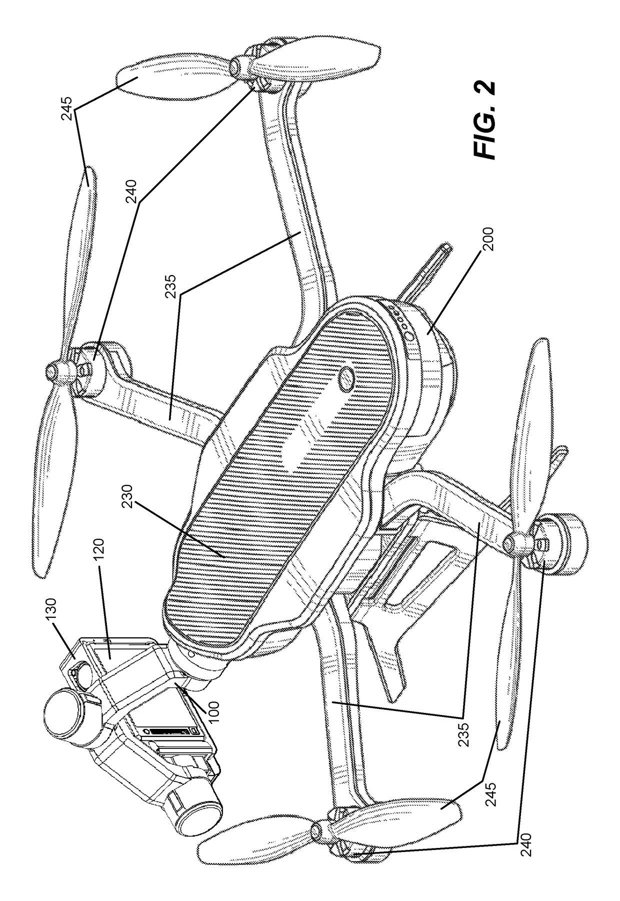
[0042]FIG. 2 illustrates an embodiment in which the mount platform 110 is an aerial vehicle 200. More specifically, the mount platform 110 in this example is a quadcopter (i.e., a helicopter with four rotors). The aerial vehicle 200 in this example includes housing 230 which encloses a payload (e.g., electronics, storage media, and / or camera), four arms 235, four rotors 240, and four propellers 245. Each arm 235 may mechanically couple with a rotor 240, which in turn couples with a propeller 245 to create a rotary assembly. When the rotary assembly is operational, all the propellers 245 may rotate at appropriate speeds to allow the aerial vehicle 200 lift (take off), land, hover, and move (forward, backward) in flight. Modulation of the power supplied to each of the rotors 240 can control the trajectory and torque on the aerial vehicle 200.

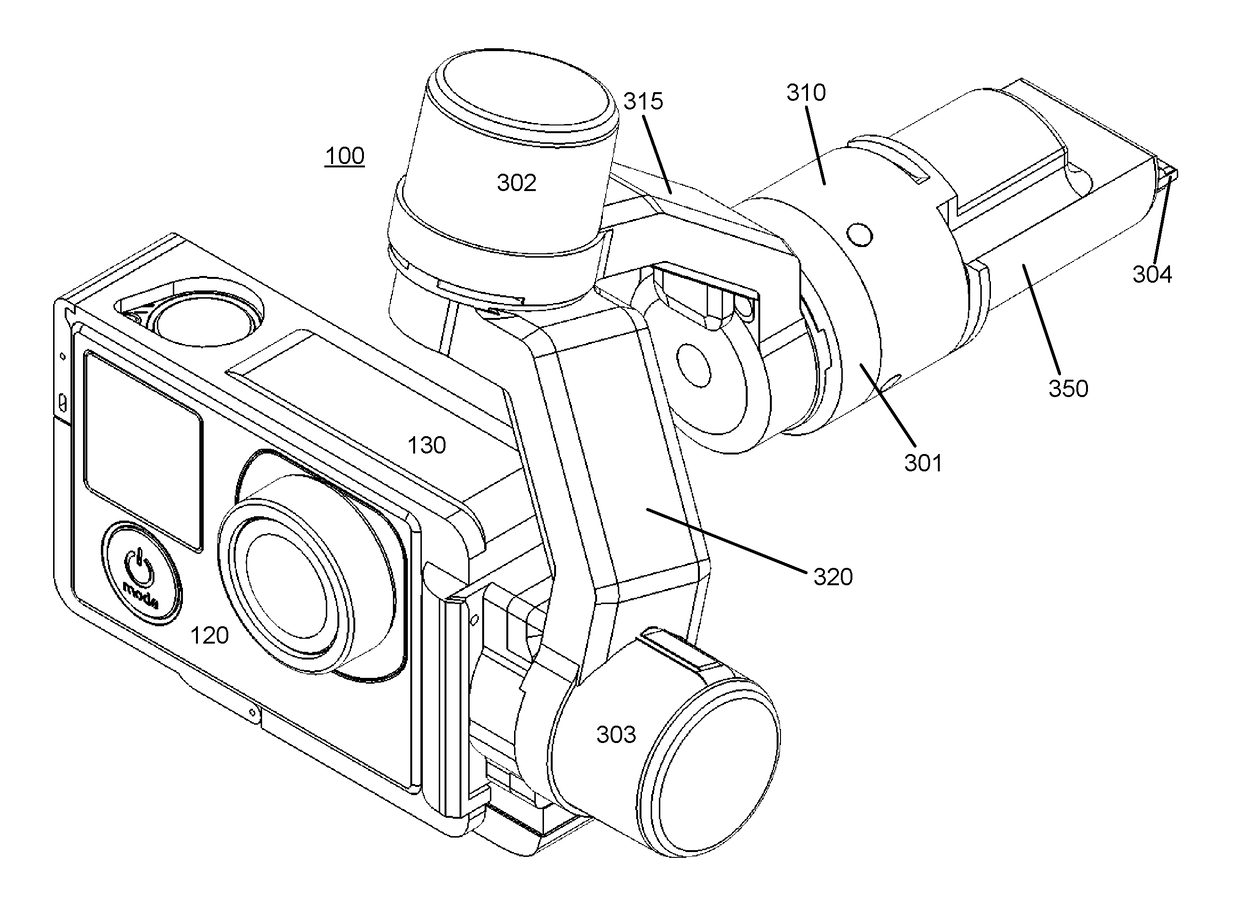
[0043]A gimbal 100 is shown coupled to the aerial vehicle 200. A camera 120 is shown enclosed in a removable camera frame 13...

example camera

Architecture

[0063]FIG. 4 illustrates a block diagram of an example camera architecture. The example camera architecture 405 corresponds to an architecture for the camera, e.g., 120. In one embodiment, the camera 120 is capable of capturing spherical or substantially spherical content. As used herein, spherical content may include still images or video having spherical or substantially spherical field of view. For example, in one embodiment, the camera 120 captures video having a 360° field of view in the horizontal plane and a 180° field of view in the vertical plane. Alternatively, the camera 120 may capture substantially spherical images or video having less than 360° in the horizontal direction and less than 180° in the vertical direction (e.g., within 10% of the field of view associated with fully spherical content). In other embodiments, the camera 120 may capture images or video having a non-spherical wide angle field of view.

[0064]As described in greater detail below, the cam...


PUM


Abstract

Disclosed is an electronic gimbal with camera and mounting configuration. The gimbal can include an inertial measurement unit which can sense the orientation of the camera and three electronic motors which can manipulate the orientation of the camera. The gimbal can be removably coupled to a variety of mount platforms, such as an aerial vehicle, a handheld grip, or a rotating platform. Moreover, a camera can be removably coupled to the gimbal and can be held in a removable camera frame. Also disclosed is a system for allowing the platform, to which the gimbal is mounted, to control settings of the camera or to trigger actions on the camera, such as taking a picture, or initiating the recording of a video. The gimbal can also provide a connection between the camera and the mount platform, such that the mount platform receives images and video content from the camera.

Description

RELATED APPLICATIONS[0001]This application claims the benefit of U.S. Provisional Patent Application No. 62 / 167,241 filed on May 27, 2015, U.S. Provisional Patent Application No. 62 / 249,879 filed on Nov. 2, 2015, and U.S. Provisional Patent Application No. 62 / 302,170 filed on Mar. 2, 2016, the contents of which are each incorporated by reference herein.BACKGROUNDField of Art[0002]The disclosure generally relates to the field of camera gimbals and in particular a detachable gimbal that can be connected to a camera and to a variety of mount platforms.Description of Art[0003]Unstabilized videos taken while flying an aerial vehicle or while moving around at ground level are often so shaky and unstable that they are unusable, not sharable, and unwatchable. The use of an electronic gimbal to stabilize or to set the orientation of a camera is known. A gimbal can be mounted to a platform such as an electronic vehicle. For example, a camera can be mounted via a gimbal to a remote control roa...

Claims


Application Information

Patent Timeline
Patent Type & Authority Applications(United States)
IPC IPC(8): F16M13/02F16M11/04G03B15/00F16M11/12G05D1/00H04N7/18F16M13/04B64C39/02B64D47/08G03B17/56F16M11/18
CPCF16M13/02G03B17/561F16M11/041G03B15/006F16M11/121B64C2201/127H04N7/183F16M13/04B64C39/024B64D47/08G05D1/0094F16M11/18H04N23/50H04N23/63H04N23/695B64U2101/30H04N5/772H04N5/783H04N9/8205H04N23/66H04N23/685H04N23/6812H04N23/55H04N23/60H04N23/11
Inventor SAIKA, NORIAKIHARRISON, RYANDRUKER, JOSHUA TODDSHUKLA, HIMAY RASHMIKANTUZUNOVIC, NENADRUSSELL, EDWARD GORDONFONG, GARY
Owner GOPRO
Why Eureka
Try Eureka