Leveraging air/water current variability for sensor network verification and source localization

a sensor network and air/water current technology, applied in the direction of fluid speed measurement, instruments, water testing, etc., can solve problems such as the form of environmental degradation

Inactive Publication Date: 2017-08-10
IBM CORP
View PDF0 Cites 22 Cited by
  • Summary
  • Abstract
  • Description
  • Claims
  • Application Information

AI Technical Summary

Problems solved by technology

This form of environmental degradation occurs when pollutants are directly or indirectly discharged into water bodies without adequate treatment to remove harmful compounds.

Method used


Image

  • Leveraging air/water current variability for sensor network verification and source localization
  • Leveraging air/water current variability for sensor network verification and source localization
  • Leveraging air/water current variability for sensor network verification and source localization

Examples


Embodiment Construction

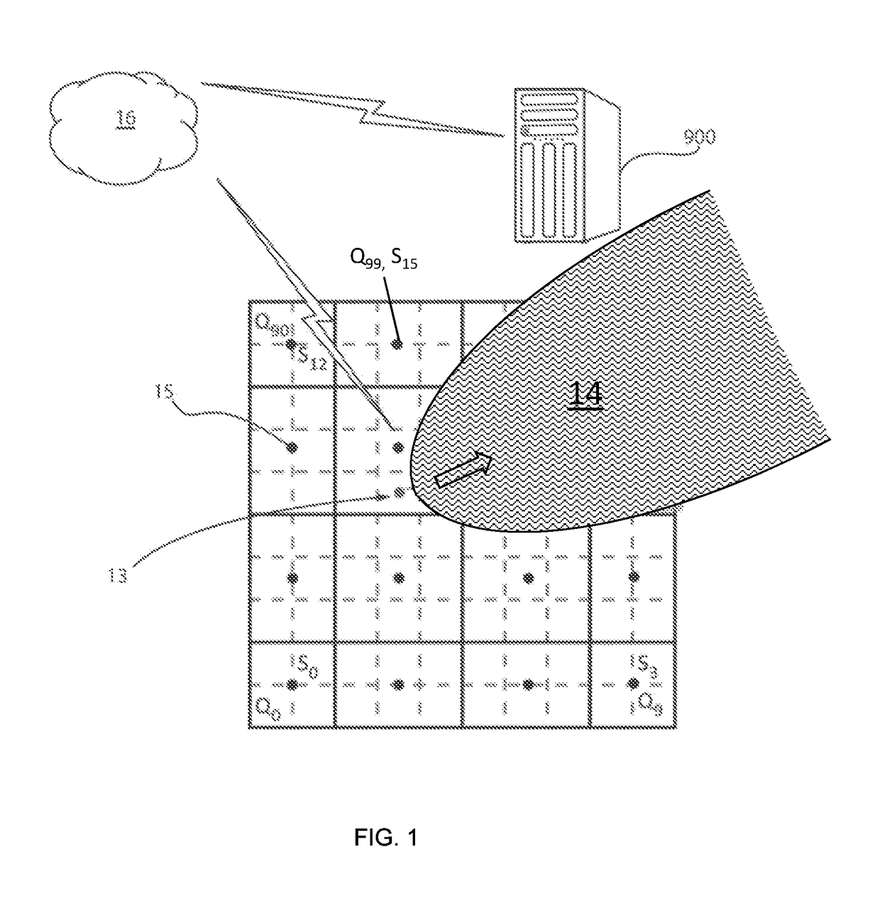
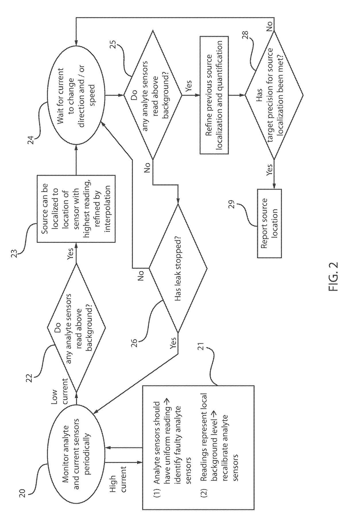
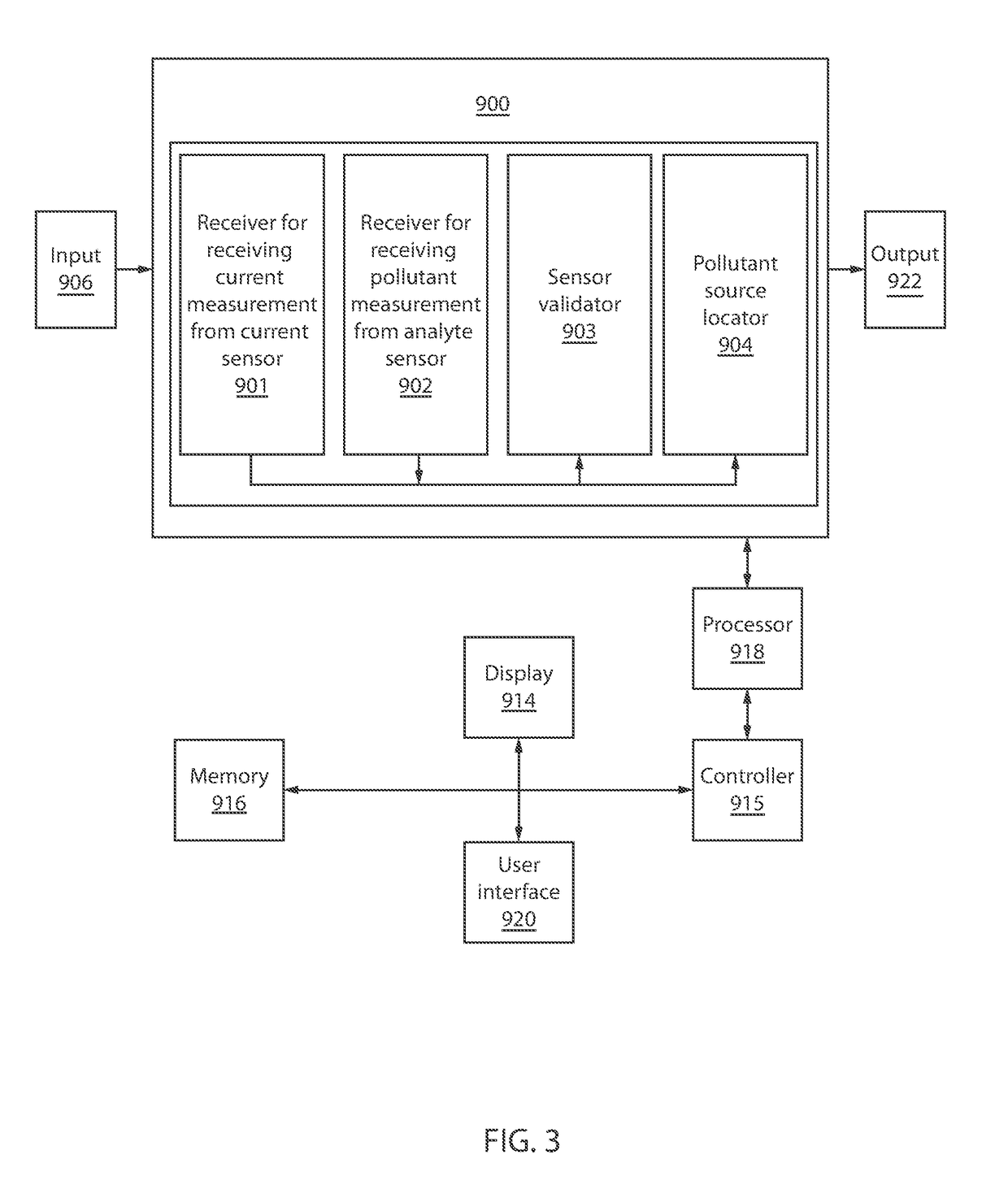
[0016]Detailed embodiments of the claimed methods, structures and computer products are disclosed herein; however, it is to be understood that the disclosed embodiments are merely illustrative of the claimed structures and methods that may be embodied in various forms. In addition, each of the examples given in connection with the various embodiments is intended to be illustrative, and not restrictive. Further, the figures are not necessarily to scale, some features may be exaggerated to show details of particular components. Therefore, specific structural and functional details disclosed herein are not to be interpreted as limiting, but merely as a representative basis for teaching one skilled in the art to variously employ the methods and structures of the present disclosure. Reference in the specification to “one embodiment” or “an embodiment” of the present principles, as well as other variations thereof, means that a particular feature, structure, characteristic, and so forth d...


PUM

PropertyMeasurementUnit
areaaaaaaaaaaa
current rateaaaaaaaaaa
dispersion modelaaaaaaaaaa

Abstract

A method for measuring pollution that includes providing a plurality of analyte sensors arranged in a grid over a sensing area, wherein the analyte sensors measure a pollutant, and positioning at least one current sensor in the sensing area. A pollution source is localized using a pollution source locator including a dispersion model and at least one hardware processor to interpolate a location of a pollution source from variations in current measured from the current sensors and measurements of pollutants from the analyte sensors.

Description

BACKGROUND[0001]Technical Field[0002]The present disclosure relates to determining the location of pollution sources, and more particularly to measuring pollution sources taking into account air and / or water current changes.[0003]Description of the Related Art[0004]Pollution technologies, including smart grid, and pollution mitigation, have become a policy focus in developed and developing nations. Air pollution is a mixture of solid particles and gases in the air. Water pollution is the contamination of water bodies (e.g. lakes, rivers, oceans, aquifers and groundwater). This form of environmental degradation occurs when pollutants are directly or indirectly discharged into water bodies without adequate treatment to remove harmful compounds.SUMMARY[0005]In one embodiment, the present disclosure provides a method of determining the source of pollutants. The method may include providing a plurality of analyte sensors arranged in a grid over a sensing area, wherein the analyte sensors...

Claims


Application Information

Patent Timeline
Patent Type & Authority Applications(United States)
IPC IPC(8): G01N33/00
CPCG01N33/0075G01N33/0036G01N33/0031G01N33/0062G01N33/007G01N33/18G01P5/00
Inventor CHANG, JOSEPHINE B.HAMANN, HENDRIK F.LU, SIYUANMURALIDHAR, RAMACHANDRANVAN KESSEL, THEODORE G.
Owner IBM CORP
Why Eureka
Try Eureka