System and Method of Patient Flow and Treatment Management

a patient flow and treatment management technology, applied in the field of real-time admission prediction and task execution, can solve the problems of inefficient mix inefficient use of these resources within a hospital, and inefficient use of paper charts and electronic medical records, so as to improve the efficiency of the admission process and reduce the time it takes

Inactive Publication Date: 2017-08-17
DISRUPTIVE IP
View PDF4 Cites 10 Cited by
  • Summary
  • Abstract
  • Description
  • Claims
  • Application Information

AI Technical Summary

Benefits of technology

[0013]In one embodiment, the present invention improves in this inefficient admission process by predicting, for each patient in the emergency department (ED), the likelihood of admission, the time until admission would occur, as well as the admitting hospital unit. Usage of this admission likelihood enables staff in interior hospital units (e.g., staff in units other than the ED unit) to prepare an appropriate bed resource in parallel with the ED workup, significantly reducing the time it takes to get a patient from the ED into a hospital unit.

Problems solved by technology

With the dramatic expansion of knowledge in medicine over the last century came an equally extensive increase in complexity in patient treatments for an ever expanding list of illnesses.
The usage of these resources within a hospital is currently poorly coordinated with manually created schedules, an inefficient mix of paper charts and electronic medical records (EMR), along with numerous phone calls, pages and voice mails.
The resulting system is very inefficient, requiring the nursing staff to spend a disproportionally large amount of their time on care coordination.
Despite these efforts patients routinely wait long hours for care, no matter if previously scheduled or not.
Nowhere else in the hospital are the problems associated with inefficient resource use and scheduling more apparent than in the emergency department (ED).
As a consequence hospitals have to, at times, go on ambulance diversion where ambulances are redirected to other (potentially more distant) facilities since the ED can not accept any more patients.
If the in-hospital unit has sent home nurses for the day already, the unit may not be able to take on any more patients from the ED even if beds would be available.
Freeing up a bed can, by itself, be a time consuming process.
During the execution of this process, the patient is ‘boarded’ in the emergency department, continuing to tie up costly resources.
As a consequence, the preparation of resources for patients that are admitted to the hospital is not started until a formal admission decision has been made, often hours after the patient arrived at the ED unit.
The problem arising from this is the extended time that admitted patients have to wait in the ED (while continuing to consume ED resources) until they can be transferred to the appropriate interior unit.
Even if patients or ambulances do call ahead, EDs often lack the ability to use “call in” information of any kind to prepare resources for their incoming patients.
They often only have limited information about the general capabilities and the current status of a given ED.
As a consequence, patients whose condition can be treated at an urgent care center may end up going to an overcrowded emergency department, enduring a long wait time while further contributing to the patient overload there.
The lack of information about emergency departments extends to emergency medical technicians (EMTs) in ambulances as well.
They generally do not have up-to-date information about current ED patient levels and sometimes even lack accurate information about the capabilities of emergency departments as shown in studies in which between 7% and 21% of trauma patients were taken to the wrong hospital.
Furthermore, patients coming to an emergency department (either on their own or in an ambulance) and the emergency department to which a patient is heading to typically know very little about each other.
As a consequence patients (and ambulances) regularly make suboptimal decisions about which facility to go to and EDs are unable to prepare resources for incoming patients.

Method used


Image

  • System and Method of Patient Flow and Treatment Management
  • System and Method of Patient Flow and Treatment Management
  • System and Method of Patient Flow and Treatment Management

Examples


Embodiment Construction

)

[0047]The present invention will now be described with reference to the accompany figures where like reference numbers correspond to like elements.

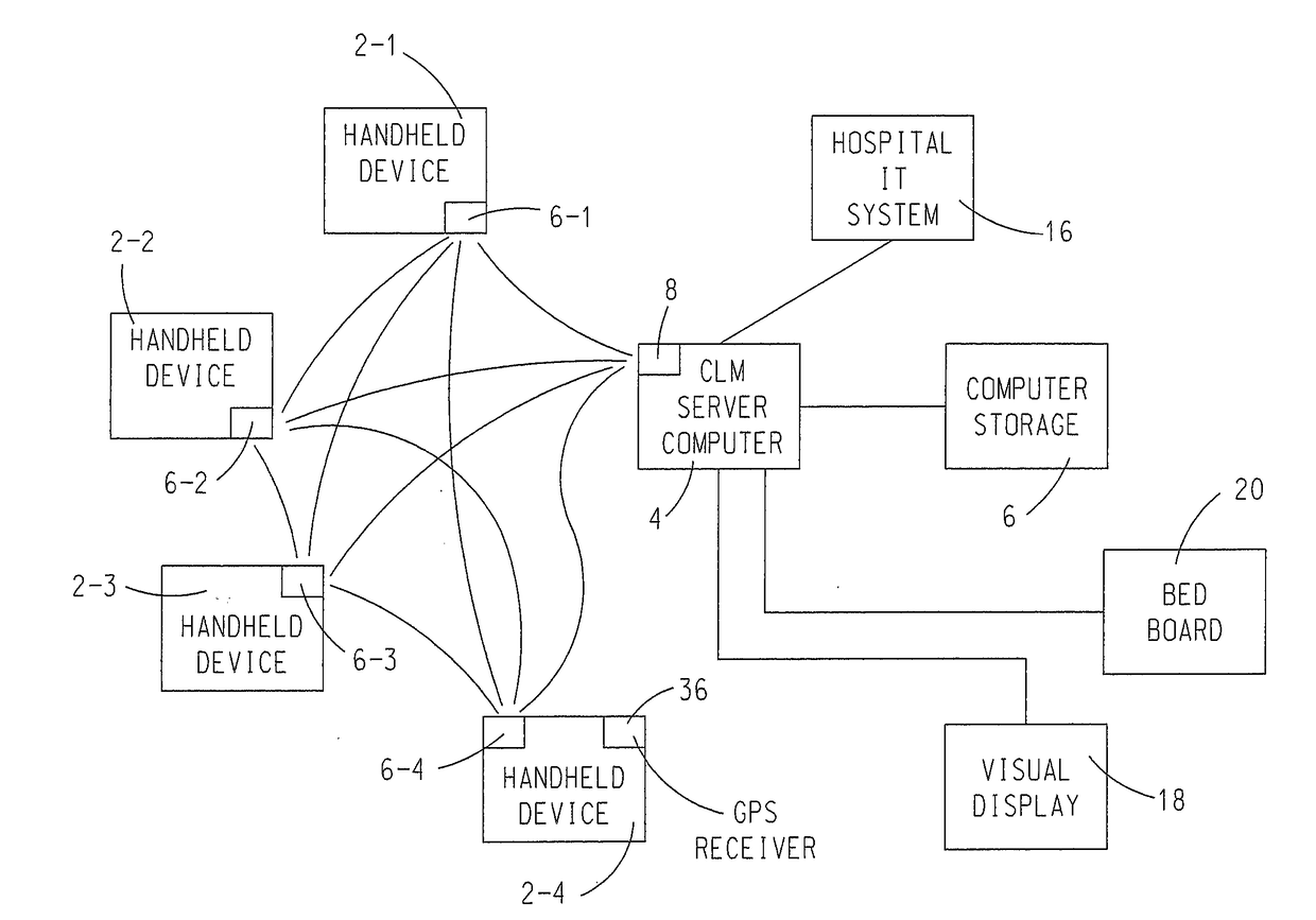
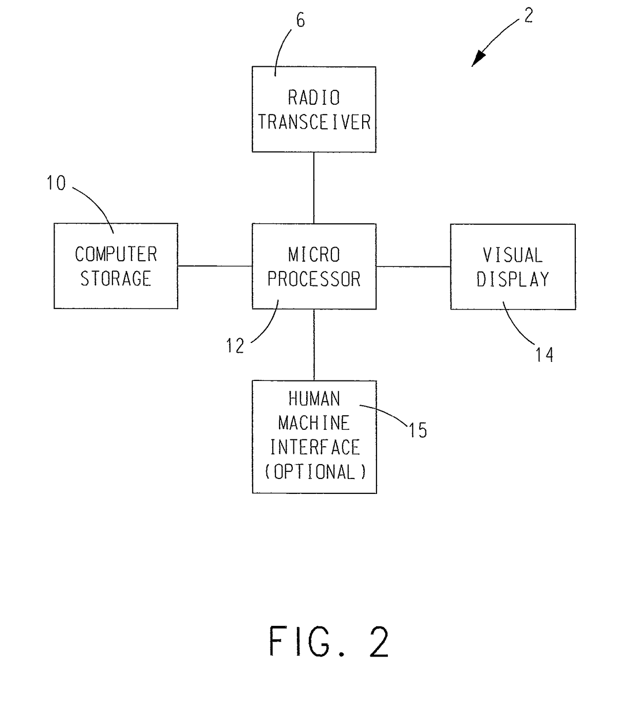
[0048]With reference to FIG. 1, an exemplary, non-limiting, system in accordance with the present invention includes a plurality of handheld or mobile devices 2 in communication with a Care Logistics Management (CLM) server computer 4 that has access to a computer storage 6. Each handheld device 2 includes a wireless transceiver 6, and CLM server 4 includes or is coupled in operative relation to a wireless transceiver 8. Each transceiver 6 is operative for establishing two-way communication with each other transceiver 6 and with transceiver 8. Similarly, transceiver 8 is operative for establishing two-way communication with each transceiver 6. The physical location of CLM server 4 and transceiver 8 is not to be construed as limiting the invention since it is envisioned that CLM server 4 and transceiver 8 can be located at or remotely fro...


PUM


Abstract

In a system and method of patient flow and treatment management, information regarding a patient admitted to a first unit of a patient treatment facility that is received into a first one of a number of user devices is dispatched to a server computer. Upon receipt of this patient information the server computer runs (desirably in real-time) a prediction application / algorithm that predicts an estimate of (1) the patient needing a resource in the first unit or a second unit of the facility, (2) a length of time before the patient needs the resource, and / or (3) an identity of the unit that has the needed resource. The server computer then dispatches (again, desirably in real-time) one or more of the predictions to one or more of the user devices, each of which receives and displays the prediction on a display thereof.

Description

CROSS REFERENCE TO RELATED APPLICATIONS[0001]This application is a continuation of U.S. patent application Ser. No. 12 / 872,434, filed August 31, 2010, which claims priority from U.S. Provisional Patient Application Nos. 61 / 238,365, filed Aug. 31, 2009, entitled “System and Method of Predicting, Planning and Managing Patient Flow in a Hospital”, and 61 / 238,420, filed Aug. 31, 2009, entitled “System and Method of Directing Patients to Treatment Appropriate Care Facilities”, all of which are incorporated herein by reference.BACKGROUND OF THE INVENTION[0002]Field of the Invention[0003]The present invention relates to real-time admission prediction and task execution in a clinical environment, such as, without limitation, a hospital emergency department. The present invention also relates to real-time direction of patients of appropriate care facilities.[0004]Description of Related Art[0005]With the dramatic expansion of knowledge in medicine over the last century came an equally extensi...

Claims


Application Information

Patent Timeline
Patent Type & Authority Applications(United States)
IPC IPC(8): G06F19/00G06Q10/06G16H30/20G16H70/20
CPCG06Q10/063114G06F19/327G06Q10/06G16H40/20G16H30/20G16H70/20
Inventor COULTER, ROBERT CRAIGGROSS, RALPHLALONDE, JEAN-FRANCOISSIMARD, BARBARA ANNE-MARIE
Owner DISRUPTIVE IP
Why Eureka
Try Eureka