
Electronic percussion instrument

a technology of e-percussion instruments and capacitance sensors, which is applied in the direction of electrophonic musical instruments, musical instruments, percussion musical instruments, etc., can solve the problems that the conventional technique described above may be different from the actual playing technique of acoustic percussion instruments, and achieve the effect of reducing the detection accuracy of capacitance sensors, preventing erroneous detection of capacitance sensors, and improving detection accuracy

Active Publication Date: 2017-08-17
ROLAND CORP
View PDF10 Cites 20 Cited by
  • Summary
  • Abstract
  • Description
  • Claims
  • Application Information

AI Technical Summary

Benefits of technology

The electronic percussion instrument described in this patent is capable of mimicking the playing technique of acoustic percussion instruments. It has a tubular body part with an open end and a head attached to the axial end surface. The instrument has a capacitance sensor with an electrode that detects changes in capacitance caused by a human body or other conductor on the front surface of the head. The electrode is located on the back surface of the head, and there is no conductor connected to the reference potential point between the front surface of the head and the electrode. This reduces the likelihood of incorrect detection of the sensor. Additionally, the instrument has a conductor part functioning as an electrostatic shield to reduce the change in capacitance caused by the approach of a conductor to the electrode on the outer side of the instrument in the axially perpendicular direction of the body part. The instrument's inclination angle can be adjusted easily, and the installation or formation work of the electrode is simplified. Finally, the instrument achieves improved detection accuracy by inclining the electrode so that its surface facing the head is inclined away from the head.

Problems solved by technology

However, the conventional technique described above may be different from the actual acoustic percussion instrument playing technique.

Method used


Image

  • Electronic percussion instrument
  • Electronic percussion instrument
  • Electronic percussion instrument

Examples


first embodiment

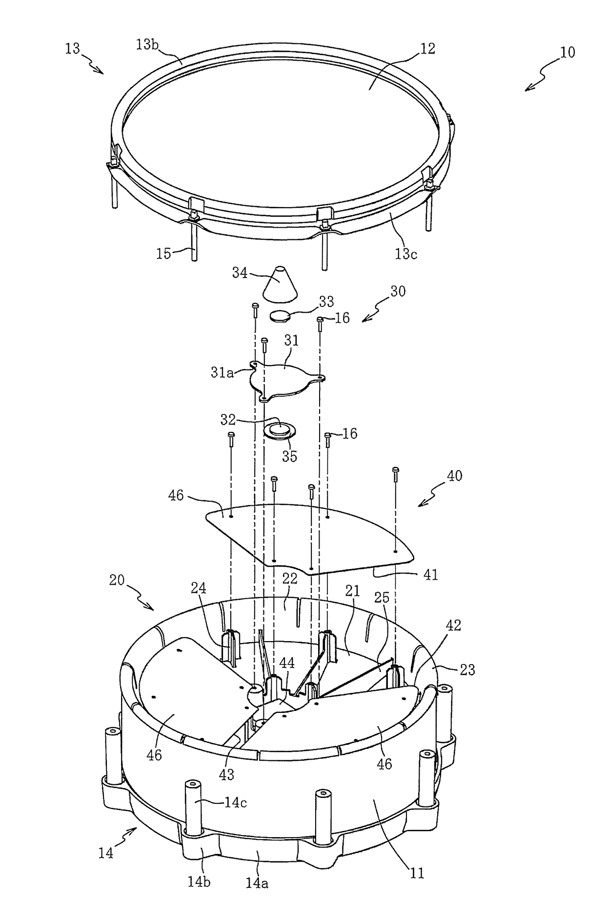
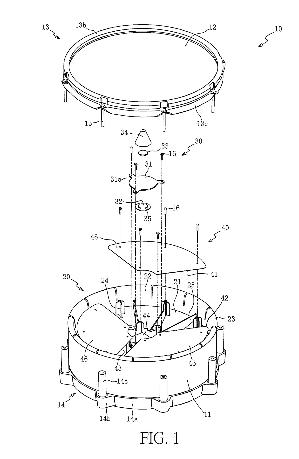
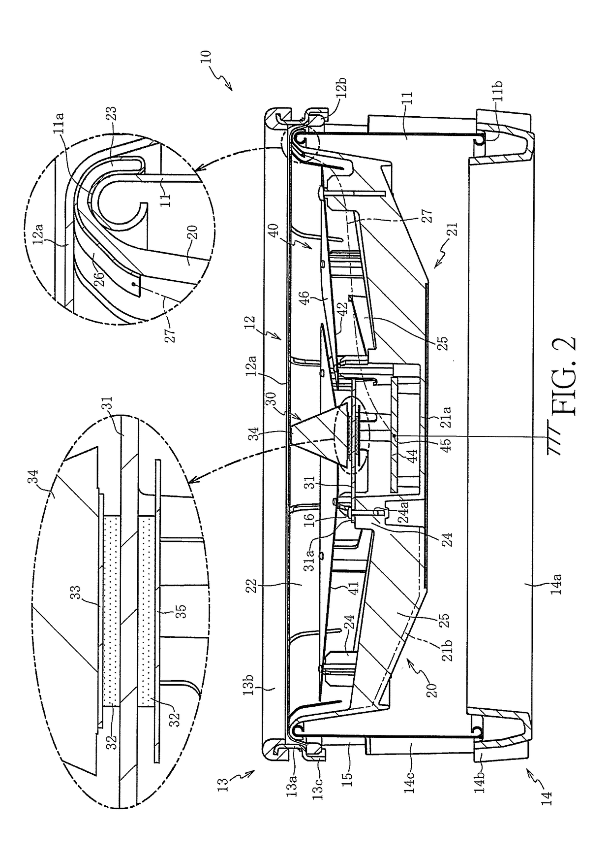
[0025]Hereinafter, exemplary embodiments of the invention are described with reference to the accompanying figures. First, an electronic percussion instrument 10 is described with reference to FIG. 1 and FIG. 2. FIG. 1 is an exploded perspective view of the electronic percussion instrument 10 according to the invention and FIG. 2 is a cross-sectional view of the electronic percussion instrument 10. With the exception of a cable 27 indicated by a dashed line in FIG. 2, other wirings are omitted from FIG. 1 and FIG. 2. Moreover, the upper side of the paper surface of FIG. 1 is defined as the top of the electronic percussion instrument 10 and the lower side of the paper surface of FIG. 1 is defined as the bottom of the electronic percussion instrument 10.

[0026]As shown in FIG. 1 and FIG. 2, the electronic percussion instrument 10 is an electronic musical instrument that simulates a drum to be played with use of a stick or the like held by a performer. The electronic percussion instrume...

second embodiment

[0078]FIG. 4 is a schematic diagram of an electronic percussion instrument 60 according to the As shown in FIG. 4, the electronic percussion instrument 60 is an electronic musical instrument that simulates a drum to be played with use of a stick or the like held by the performer. In the electronic percussion instrument 60, the first electrode 62, the second electrode 63, and the third electrode 64 are arranged in this order from the sensor part 30 to the rim 13 (the shell 11). Each of the electrodes 62, 63, and 64 is an electrode disposed in a self-capacitance type capacitance sensor 61, and is formed of an annular conductor centered on the axial center of the rim 13.

[0079]An inner diameter of the first electrode 62 is set so that the first electrode 62 does not interfere with the sensor part 30. An inner diameter of the second electrode 63 is set greater than an outer diameter of the first electrode 62. An inner diameter of the third electrode 64 is set greater than an outer diame...

third embodiment

[0082]FIG. 5 is a cross-sectional view of an electronic percussion instrument 70 according to the As shown in FIG. 5, the electronic percussion instrument 70 is an electronic musical instrument that simulates a drum to be played with use of a stick or the like held by the performer. A frame 71 of the electronic percussion instrument 70 is a bowl-shaped member for disposing various members inside the shell 11, and the frame 71 is formed of a synthetic resin (insulator). The frame 71 includes the bottom part 72, a sidewall part 22, and a hook part 23. The bottom part 72 is disposed at a predetermined distance from the head 12. The sidewall part 22 rises from the outer peripheral edge of the bottom part 72. The hook part 23 is formed on the outer peripheral edge of the sidewall part 22.

[0083]The bottom part 72 includes an inclined part 73, a central part 74, and a recessed part 75. The inclined part 73 is connected to the sidewall part 22 on the outer peripheral edge. The central part...


PUM


Abstract

Provided is an electronic percussion instrument that is capable of simulating a playing technique for an acoustic percussion instrument. A tubular body part is opened on an axial end surface, and a head is attached to the axial end surface to be struck on the front surface. A capacitance sensor includes an electrode that generates a capacitance with respect to a detected conductor, such as a human body, positioned on the front surface side of the head. Because the capacitance sensor detects a change of a capacitance corresponding to a distance between the electrode and the detected conductor, whether the detected conductor approaches (contacts) the head or presses the head can be determined. As a result, the playing technique for the acoustic percussion instrument is simulated.

Description

CROSS-REFERENCE TO RELATED APPLICATION[0001]This application claims the priority benefit of Japanese patent application no. 2016-028149, filed on Feb. 17, 2016. The entirety of the above-mentioned patent application is hereby incorporated by reference herein and made a part of this specification.BACKGROUND OF THE INVENTION[0002]Field of the Invention[0003]The invention relates to an electronic percussion instrument and more particularly relates to an electronic percussion instrument that is capable of simulating a playing technique for an acoustic percussion instrument.[0004]Description of Related Art[0005]There are conventional electronic percussion instruments that simulate acoustic percussion instruments, such as drums, in which the open end of a shell is covered by a head and the outer edge ring of the head is pressed and fixed by an annular rim. Open rim shot and closed rim shot are playing techniques for acoustic percussion instruments. Open rim shot is to strike the rim and t...

Claims


Application Information

Patent Timeline
Patent Type & Authority Applications(United States)
IPC IPC(8): G10H3/14G10H3/10G10D13/02
CPCG10H3/146G10D13/024G10H2230/315G10H2230/301G10H2230/311G10H3/10G10H2230/275G10H1/0551G10H2230/285G10D13/02G10D13/26
Inventor TAKASAKI, RYOYOSHIKUNI, NORIHIROOSADA, TAKESHIMORITA, YUTAKA
Owner ROLAND CORP
Learn More