Image scanning apparatus, control method therefor, and multifunction apparatus

a multi-functional, scanning apparatus technology, applied in the direction of electrical apparatus, pictures, etc., can solve the problems of increasing cost, ineffective use of resources such as afe at the time of high-resolution interval output, etc., and achieve the effect of increasing scanning speed and increasing cos

Active Publication Date: 2017-08-17
CANON KK
View PDF2 Cites 4 Cited by
  • Summary
  • Abstract
  • Description
  • Claims
  • Application Information

AI Technical Summary

Benefits of technology

[0006]The present invention has been made in consideration of the conventional techniques, and increases the scanning speed at the time of sin

Problems solved by technology

The image scanning apparatus described in Japanese Patent Laid-Open No. 2009-188485 poses a problem that resources such as an AFE cannot effectively be used at the time of high-resol

Method used


Image

  • Image scanning apparatus, control method therefor, and multifunction apparatus
  • Image scanning apparatus, control method therefor, and multifunction apparatus
  • Image scanning apparatus, control method therefor, and multifunction apparatus

Examples


first embodiment

[0029]The first embodiment of the present invention will be described below.

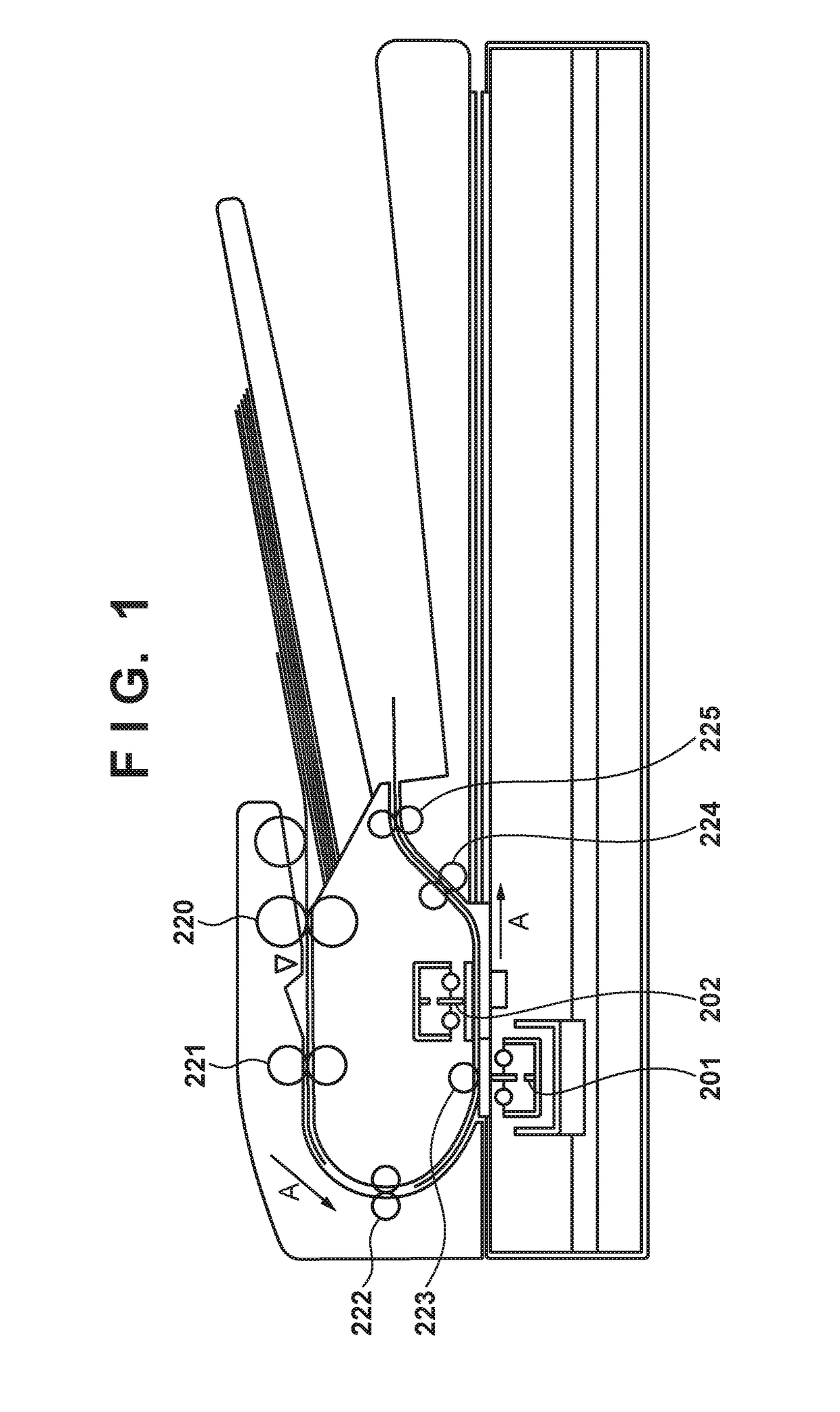
[0030]FIG. 1 is a side sectional view showing an image scanning apparatus as an example according to the present invention. The image scanning apparatus according to this embodiment will be described as an apparatus having an arrangement capable of scanning both sides of a scanning target original in parallel. In other words, in this embodiment, the scanning processing of the front surface of the scanning target original and that of the back surface of the original can be executed in parallel.

[0031]As shown in FIG. 1, the image scanning apparatus includes a front surface scanner unit 201, a back surface scanner unit 202, and conveyance rollers 220 to 225 for conveying an original. The front surface scanner unit (CIS1) 201 is a device for scanning an image printed on the front surface of the original, and the back surface scanner unit (CIS2) 202 is a device for scanning an image printed on the back surface of...

second embodiment

[0088]The second embodiment of the present invention will be described.

[0089]FIG. 12 shows an example of the arrangement of an image scanning apparatus according to the second embodiment of the present invention.

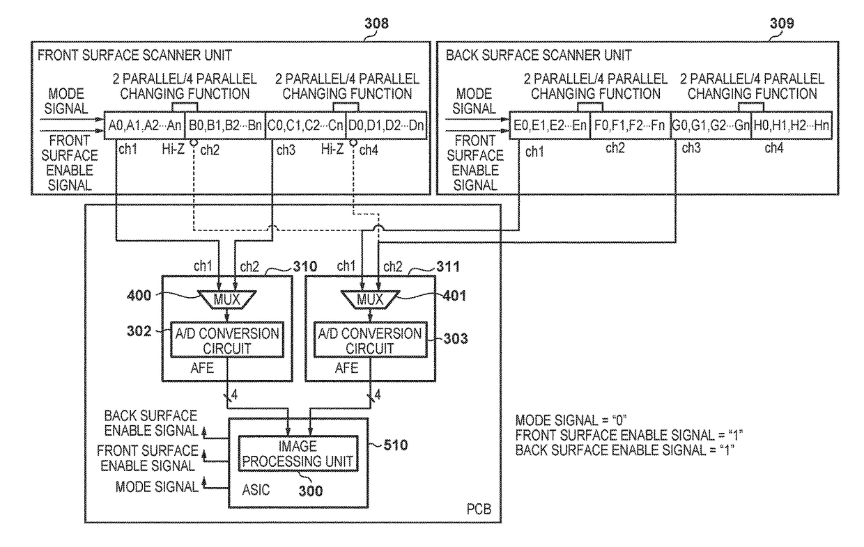
[0090]In this embodiment, one AFE and two scanner units (CISs) are included. An AFE 320 can input analog image data of four channels from a front surface scanner unit 308 and analog image data of two channels from a back surface scanner unit 309, that is, analog image data of six channels in total. That is, the number of input channels of the AFE 320 is given by the sum of the maximum number of output channels from which the front surface scanner unit 308 can output data and the number of output channels from which the back surface scanner unit 309 outputs data at the time of both-sided scanning. Furthermore, in accordance with a mode signal input from an ASIC 510, an MUX 450 selects two channels from the input signals of the six channels. A / D conversion circuits 350 and 351...


PUM


Abstract

An image scanning apparatus comprises: a first image scanning unit that performs image scanning of a first surface of an original; a second image scanning unit that performs image scanning of a second surface of the original; and a control unit that controls output channels for outputting analog signals from the first image scanning unit, wherein the control unit changes, between a case of single-sided scanning and a case of both-sided scanning, the output channels of the analog signals output from a part of scanning region in a plurality of scanning regions of the first image scanning unit, and changes, between a case of single-sided scanning and a case of both-sided scanning, the number of output channels for outputting the analog signals from the first image scanning unit.

Description

BACKGROUND OF THE INVENTION[0001]Field of the Invention[0002]The present invention relates to an image scanning apparatus, a control method therefor, and a multifunction apparatus.[0003]Description of the Related Art[0004]In recent years, it has been required to increase the scanning speed of an image scanning apparatus. To satisfy this requirement, Japanese Patent Laid-Open No. 2009-188485 proposes a method of parallelly outputting image sensor outputs. Furthermore, Japanese Patent Laid-Open No. 2006-279112 proposes a method in an image scanning apparatus capable of concurrent both-sided scanning.[0005]The image scanning apparatus described in Japanese Patent Laid-Open No. 2009-188485 poses a problem that resources such as an AFE cannot effectively be used at the time of high-resolution interval output. Furthermore, the image scanning apparatus described in Japanese Patent Laid-Open No. 2006-279112 needs to have two conveyance paths, thereby increasing the cost.SUMMARY OF THE INVEN...

Claims


Application Information

Patent Timeline
IPC IPC(8): H04N1/203H04N1/00
CPCH04N1/2034H04N2201/0081H04N2201/0094H04N1/00822H04N1/203H04N1/2032
Inventor WATANABE, EIJI
Owner CANON KK
Why Eureka
Try Eureka