
Automatic Lifting Device for Toaster Carrier

a lifting device and toaster carrier technology, applied in the field of toasters, can solve problems such as affecting usage, and achieve the effects of convenient operation, high degree of automation, and useful and reliable structur

Inactive Publication Date: 2017-08-24
KINWING ELECTRIC IND
View PDF3 Cites 4 Cited by
  • Summary
  • Abstract
  • Description
  • Claims
  • Application Information

AI Technical Summary

Benefits of technology

The technical effect of this utility model is to provide an automatic lifting device for a toaster carrier, which improves positioning accuracy in rising and lowering the carrier, and makes the structure more useful and reliable. The device is controlled by a motor that drives the rocker arm to rotate, which in turn drives the slide seat to rise and fall, allowing for automatic control of the carrier. The degree of automation is high, the structure is reliable and convenient to operate, and the control manner is easy to implement, while the production cost is lower.

Problems solved by technology

However, this control manner that realized by rising up and lowering a carrier to trigger the limit switches is less accurate, which may make the bread not to be lifted to the desired height and may affect the usage.

Method used


Image

  • Automatic Lifting Device for Toaster Carrier
  • Automatic Lifting Device for Toaster Carrier
  • Automatic Lifting Device for Toaster Carrier

Examples


first embodiment

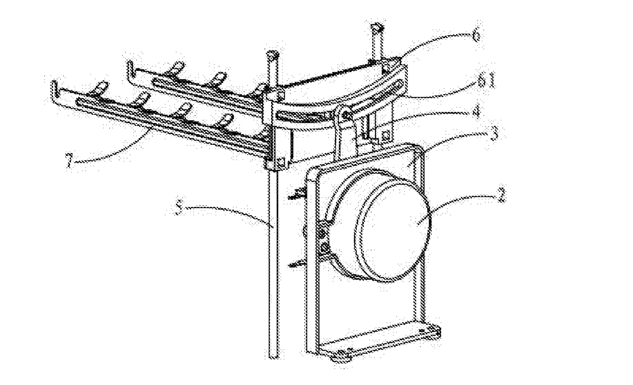
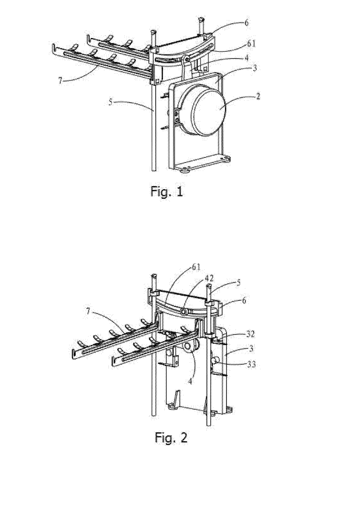
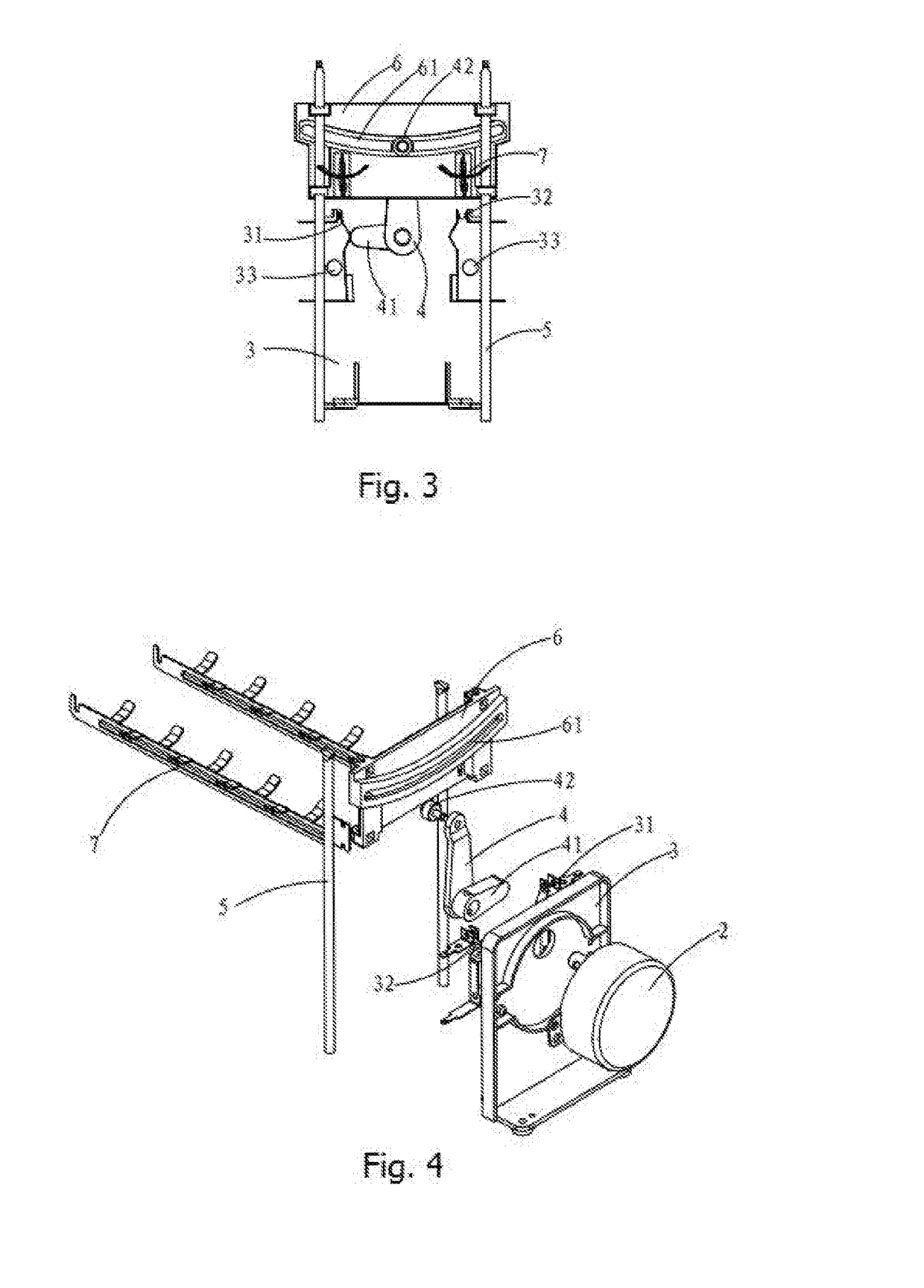
[0025]Referring to FIGS. 1-4, in the first embodiment, an upper trigger switch 31 and a lower trigger switch 32 are respectively provided on the left and right side of the rocker arm 4 and the two switches are arranged to be opposite to each other, the triggering directions of the two switches are parallel to the motor mounting base 3, the end of the cam 41 far away from the output shaft is arc-shaped, during swinging of the cam 41 in joint movement with the rocker arm 4, when the cam 41 rotates to a corresponding position of the upper trigger switch 31 or the lower trigger switch 32, the end of the cam 41 touches the metal shrapnel, and then the metal shrapnel is pressed to trigger the corresponding switch to control the motor 2 to stop running.

[0026]In the embodiment, limiting posts 33 for limiting the positions of shrapnels are respectively arranged on the motor mounting base 3 corresponding to the upper trigger switch 31 and the lower trigger switch 32, and the limiting posts 33...

second embodiment

[0027]Referring to FIG. 5, in the second embodiment, an upper trigger switch 31 and a lower trigger switch 32 are respectively provided on the left and right side of the rocker arm 4, the two switches are fixed on the motor mounting base 3 in parallel and positioned in the rotation range of the cam 41, the triggering directions of the two switches are perpendicular to the motor mounting base 3. In this embodiment, the side edge of the cam 41 is provided with an arc-shaped edge so as to press the metal shrapnels of the switches. During swinging of the cam 41 in joint movement with the rocker arm 4, when the cam 41 rotates to the corresponding position of the upper trigger switch 31 or the lower trigger switch 32, the side edge of the cam 41 touches the metal shrapnel, and then the metal shrapnel is pressed to trigger the corresponding switch to control the motor 2 to stop running

[0028]Referring to FIG. 6, when in operation, when the motor 2 drives the bread carriers 7 to fall down to...


PUM


Abstract

The utility model discloses an automatic lifting device for a toaster carrier, comprising a machine base, carriers, sliding guide pillars, a slide seat, a rocker arm, a motor and a motor mounting base. The motor is fixed on the motor mounting base, and an output rotation shaft of the motor is connected with the slide seat via the rocker arm. The motor mounting base is provided with an upper trigger switch and a lower trigger switch corresponding to swinging positions of the cam. The motor drives the rocker arm to rotate so as to drive the slide seat to rise and fall, thus the automatic control of the rising and falling of the carriers is achieved.

Description

TECHNICAL FIELD[0001]The utility model relates to the technical field of toasters, in particular to an automatic lifting device for a toaster carrier.BACKGROUND ART[0002]The toaster is an electrically heated cooker which is mainly used for toasting a sliced bread, and by which not only can toast the sliced bread into light brown, but also improve its flavor and taste to whet the appetite. A toaster with a function of automatically lifting the bread is commercially available with the following working process: placing a bread in a bread slot of the toaster; controlling and lowering a carrier to the bottom of the bread slot, at this point a switch is triggered to turn on the power and a heating wire starts to work for heating and roasting; after a set time of the roasting is reached, the heating wire is switched off; and a motor drives the carrier to rise up to lift the bread, and the roasting is completed. In a structure of such toasters, generally an upper limit switch and a lower l...

Claims


Application Information

Patent Timeline
Patent Type & Authority Applications(United States)
IPC IPC(8): A47J37/08
CPCA47J37/0821
Inventor MAO, SAM
Owner KINWING ELECTRIC IND
Learn More