
Eureka
For R&D, Eureka makes reading and utilizing patents & technical documents easy.
Eureka AIR
Designed for self-driven R&D workflows. Generate viable solutions, solve complex R&D challenges, empower your innovation with AI.

Eureka Materials
Designed for material experts only. Revolutionize your material R&D, from search, analyze, to developing new materials.

TechResearch
Generate reliable direction feasibility study reports for your R&D in just a few steps.

TechSeek
Discover and master advanced knowledge NOW. Basics, ideas, possibilities, all at once.

TechMind
As an expert in R&D Theories, TechMind can generates customized viable solutions instantly.

TechRisk
Analyze your overall solution with one click, know your potential R&D risks in advance.

TechMonitor
Get weekly tech updates, stay abreast of the latest tech innovations and key insights.
Railroad Coupler Knuckle with External Weight Reducing Features and Method of Forming the Same
- Summary
- Abstract
- Description
- Claims
- Application Information
AI Technical Summary
Benefits of technology
Problems solved by technology
Method used
Image

Examples
Embodiment Construction
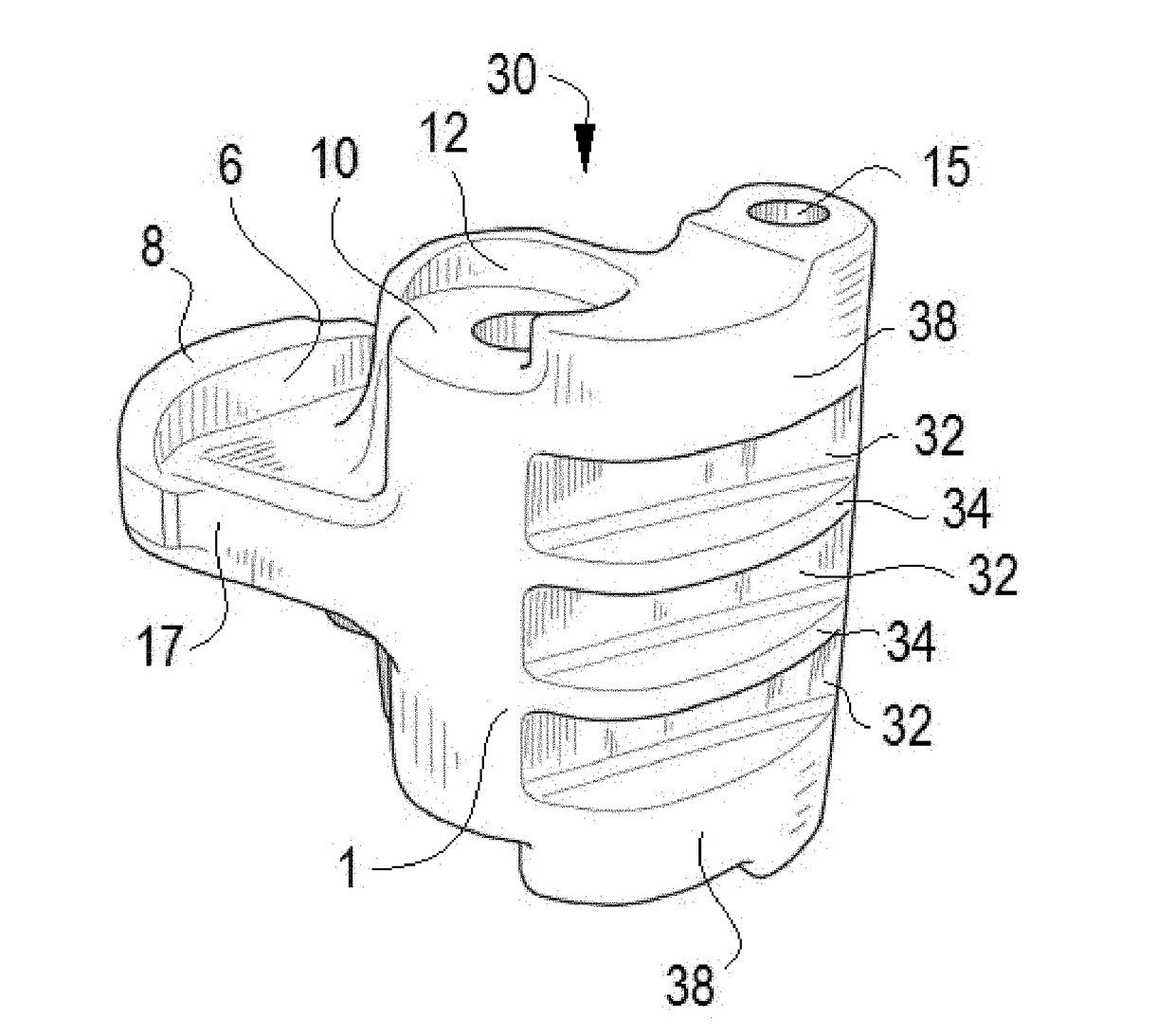
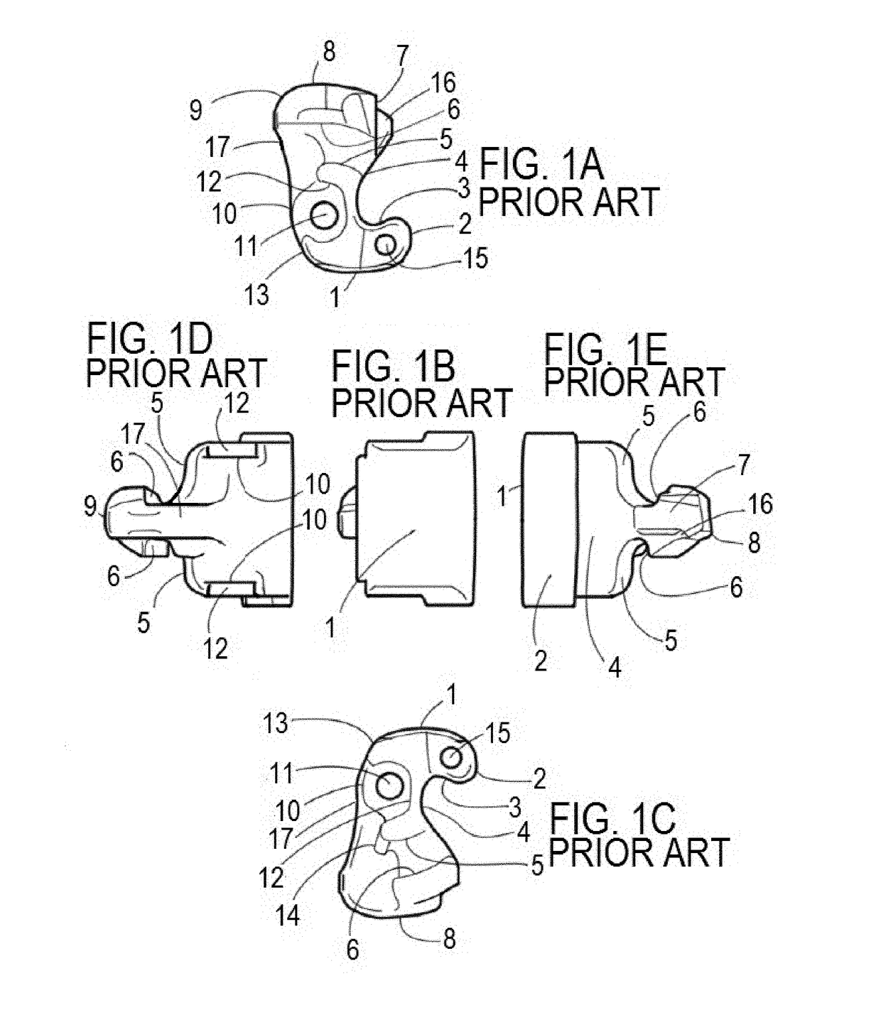
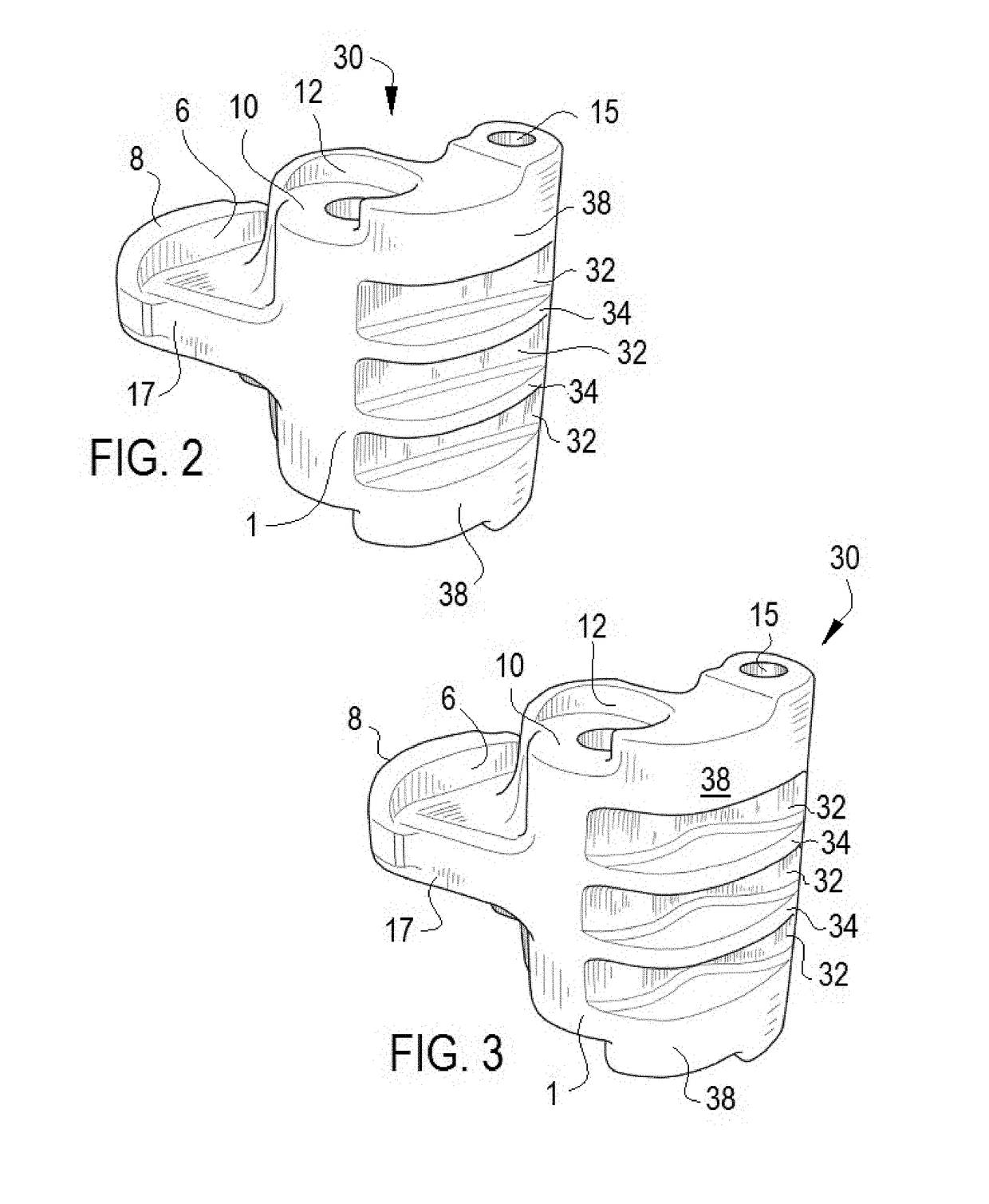
[0033]A conventional E-type coupler knuckle is well known to those of ordinary skill in the art, however it may be illustrative to review the structure of a conventional coupler to explain the present invention and the positioning of the weight saving external features of the present invention.
[0034]A conventional E-type coupler knuckle, as shown in FIGS. 1A-E, includes a front face 1, which can be described as one of the surfaces of the knuckle that transmits the buff forces of the train. For reference the buff forces are the compressive forces (e.g., the cars coming together) and draft forces are the tensile forces (e.g., the cars moving apart). The nose 2 of the conventional e-type coupler knuckle is the primary contour of the knuckle that allows the coupler to mate with the adjacent coupler (via coupler knuckle rotated 180 degrees about a vertical axis).
[0035]The pulling face 3 is the surface of the knuckle that transmits the draft forces through coupler. The throat 4 of the knu...
PUM
 Abstract
Description
Claims
Application Information
 - R&D Engineer
- R&D Manager
- IP Professional
- Industry Leading Data Capabilities
- Powerful AI technology
- Patent DNA Extraction
Browse by: Latest US Patents, China's latest patents, Technical Efficacy Thesaurus, Application Domain, Technology Topic, Popular Technical Reports.
© 2024 PatSnap. All rights reserved.Legal|Privacy policy|Modern Slavery Act Transparency Statement|Sitemap|About US| Contact US: help@patsnap.com