Energy-saving dyeing machine

a dyeing machine and energy-saving technology, applied in the direction of the driving mechanism of the machine, textile treatment, liquid/gas/vapor treatment, etc., to achieve the effect of saving several heating procedures and unnecessary energy waste, and better use of heat energy

Active Publication Date: 2017-08-24
TAI SU ENERGY TECH CO LTD
View PDF1 Cites 3 Cited by
  • Summary
  • Abstract
  • Description
  • Claims
  • Application Information

AI Technical Summary

Benefits of technology

[0012]As stated above, the present invention has the direct-heating heat exchanger to heat up liquid dyes by the heated gas, saving several heating procedures and unnecessary energy wa

Problems solved by technology

However, after conducting the direct heating, the exhaust gas is discharged immediately, which becom

Method used


Image

  • Energy-saving dyeing machine
  • Energy-saving dyeing machine
  • Energy-saving dyeing machine

Examples


Embodiment Construction

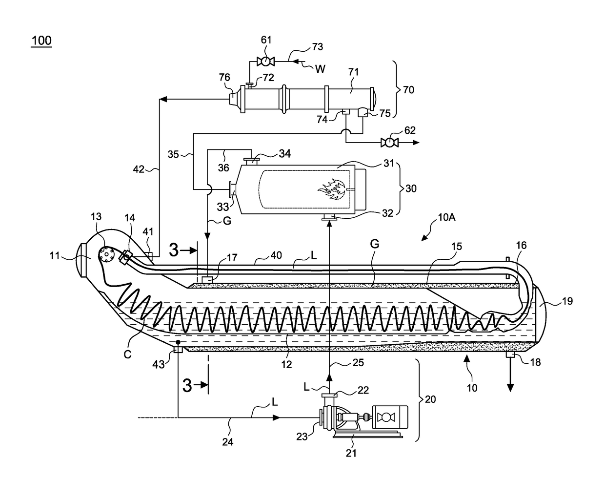
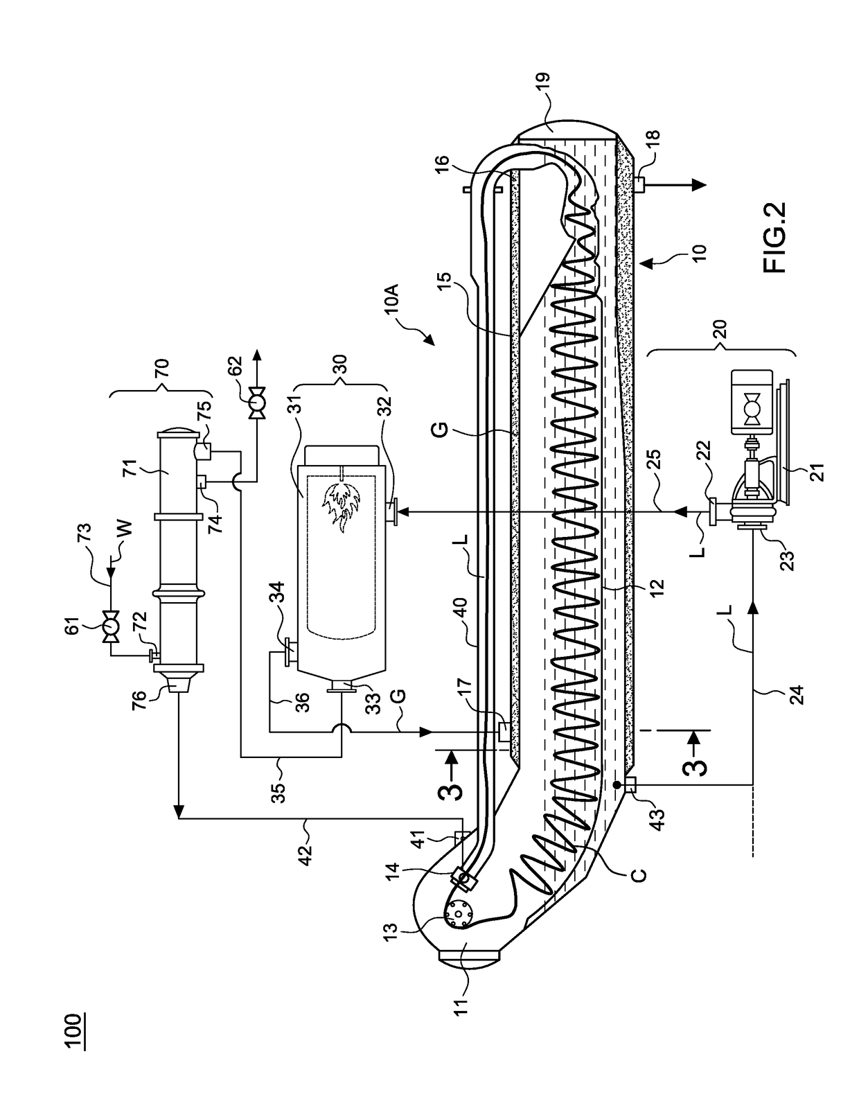
[0019]Referring to FIG. 2, in an applicable embodiment, a horizontal energy-saving dyeing machine 100 mainly includes a body 10, a guiding tube 40, a liquid dyes supply device 20, a liquid dyes heating device 30, and a cooling unit 70. In this embodiment, the body 10 is horizontally arranged but it is not limited to such application. It can be vertically arranged as well.

[0020]The body 10 includes a head portion 11, a storage tank 12, an entering port for liquid dyes 41 arranged above, connecting to an entering tube 42, and an exiting port for liquid dyes 43 arranged below, connecting to an exiting tube 24. The head portion 11 further includes a rolling reel 13 and a nozzle 14 connecting to the entering port for liquid dyes 41. The guiding tube 40 links the nozzle 14 to a rear section 19 of the body 10 for circulation dipping.

[0021]The features of the present invention are described as following. The body 10 further includes an outer wall 15 to define a surrounding space 16 for heat...


PUM


Abstract

An energy-saving dyeing machine includes a body, a liquid dyes supply device, a liquid dyes heating device having a direct-heating heat exchanger, and a cooling unit connecting to the direct-heating heat exchanger by a series connection. When heating up the liquid dyes, the liquid dyes enters the direct-heating heat exchanger from the liquid dyes supply device via a supply tube, saving several heating procedures and unnecessary energy wastes. Additionally, an outer wall is surrounding the body to form a surrounding space for the heated exhaust gas from the direct-heating heat exchanger to enter and reheat the liquid dyes in the body again, making a better use of the heat energy.

Description

BACKGROUND OF THE INVENTION[0001]1. Field of the Invention[0002]The present invention relates to a dyeing machine, particularly to one that has a direct-heating heat exchanger to heat up liquid dyes and further heats up the liquid dyes in a body thereof by the heated exhaust gas in order to make a better use of the heat energy and reduce unnecessary wastes.[0003]2. Description of the Related Art[0004]A conventional dyeing machine has structures as shown in FIG. 1, mainly including a body (110), a liquid dye supply device (120), and a guiding tube (140). The bodying has a head portion (111) with a rolling reel (113) and a nozzle (114), and a storage tank (112). The liquid dye supply device (120) sucks in liquid dyes by a main pump (121) and a dosing pump (123) from a dosing tank (122) to flow through a heat exchanger (130) via a linking tube (124) to the nozzle (114). The guiding tube (140) links the nozzle (114) to the rear of the body (110), forming a routine for a piece of fabric ...

Claims


Application Information

Patent Timeline
IPC IPC(8): D06B23/22D06B3/34D06B3/22
CPCD06B23/22D06B2700/095D06B3/34D06B3/22D06B3/28
Inventor LIAO, CHIU-HUEI
Owner TAI SU ENERGY TECH CO LTD
Why Eureka
Try Eureka