Method and apparatus for steering a drill string and reaming well bore surfaces nearer the center of drift

Inactive Publication Date: 2017-08-24
EXTREME TECH
View PDF10 Cites 8 Cited by
  • Summary
  • Abstract
  • Description
  • Claims
  • Application Information

AI Technical Summary

Benefits of technology

[0010]Accordingly, a need exists for a reamer that reduces the torque and drag on the drill string and produces closer to drift well bore. A need also exists for a reamer capable of enlarging the diameter

Problems solved by technology

Repeated correcting of the direction of the well bore causes micro-ledging and “doglegs,” inducing friction and drag between the well bore and the bottom hole assembly and drill string.
This undesired friction causes several negatives on the drilling process, including but not limited to: increasing torque and drag, ineffective weighting on bit transfer, eccentric wearing on the drill string and bottom hole assembly (BHA), increasing the number of days to drill the well, drill string failures, limiting the distance the well bore can be extended, and issues related to inserting the

Method used


Image

  • Method and apparatus for steering a drill string and reaming well bore surfaces nearer the center of drift
  • Method and apparatus for steering a drill string and reaming well bore surfaces nearer the center of drift
  • Method and apparatus for steering a drill string and reaming well bore surfaces nearer the center of drift

Examples


Embodiment Construction

[0028]As embodied and broadly described, the disclosures herein provide detailed embodiments of the invention. However, the disclosed embodiments are merely exemplary of the invention that may be embodied in various and alternative forms. Therefore, there is no intent that specific structural and functional details should be limiting, but rather the intention is that they provide a basis for the claims and as a representative basis for teaching one skilled in the art to variously employ the present invention.

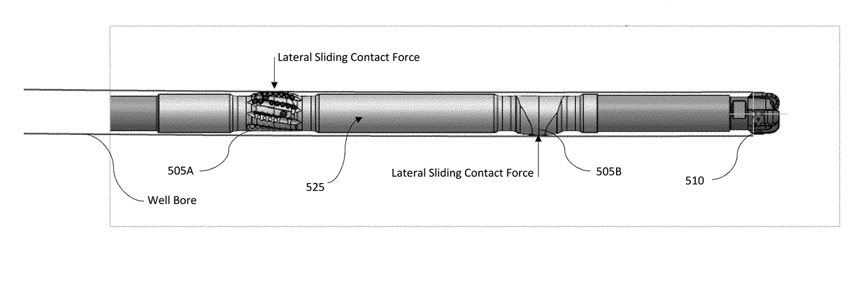
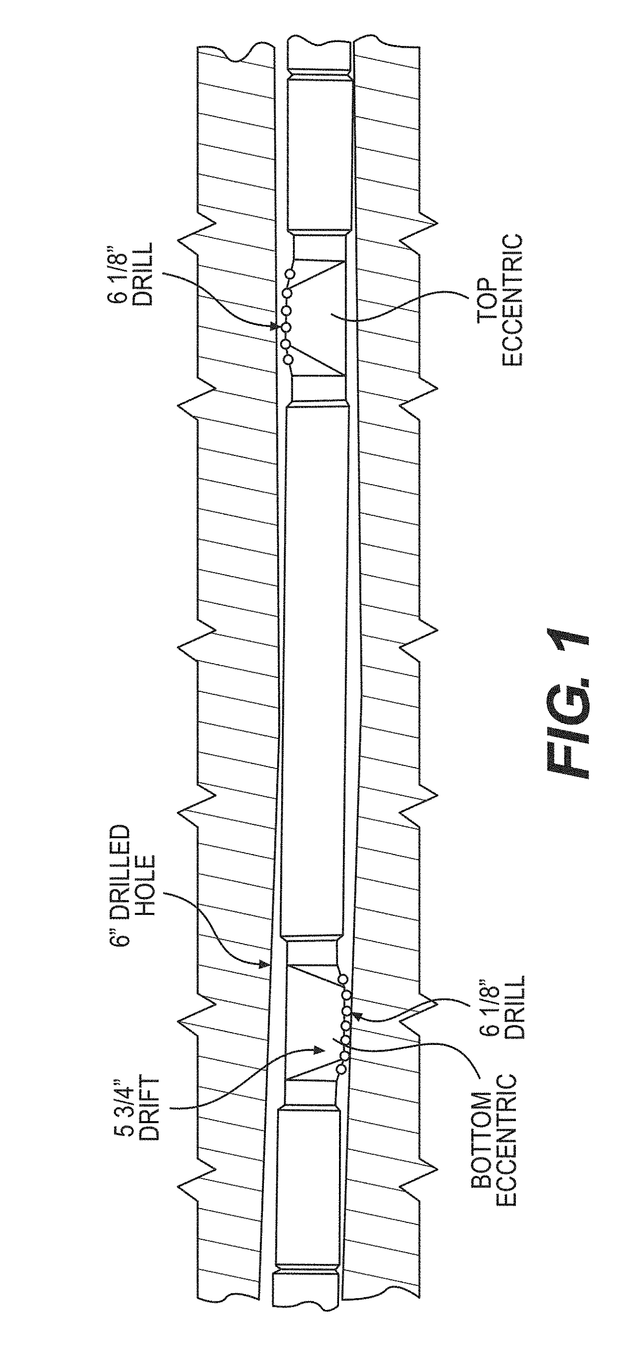
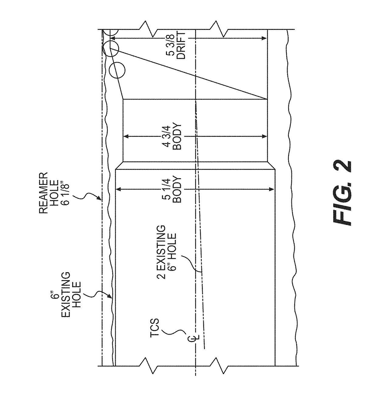
[0029]A problem in the art capable of being solved by the embodiments of the present invention is increasing the drift diameter of a well bore. It has been surprisingly discovered that providing diametrically opposed reamers allows for improved reaming of well bores compared to conventional reamers. This is accomplished, in one embodiment, by cutting away material primarily forming surfaces nearer the center of the drift. Doing so reduces applied power, applied torque and result...


PUM


Abstract

A steerable well bore drilling device and method are disclosed. The steerable well bore drilling device comprises a drill string, a bit coupled to the drill string, a drilling motor within the drill string and driving the bit, and a pair of eccentric reamers coupled to the drill string and positioned between the bit and the motor.

Description

REFERENCE TO RELATED APPLICATIONS[0001]This application is a continuation-in-part of U.S. non-provisional application Ser. No. 14 / 298,484, filed Jun. 6, 2014, entitled “METHOD AND APPARATUS FOR REAMING WELL BORE SURFACES NEARER THE CENTER OF DRIFT, which is a continuation of U.S. non-provisional application Ser. No. 13 / 442,316, filed Apr. 9, 2012, entitled “METHOD AND APPARATUS FOR REAMING WELL BORE SURFACES NEARER THE CENTER OF DRIFT,” which claims priority to U.S. provisional application Ser. No. 61 / 473,587, filed Apr. 8, 2011, entitled “METHOD AND APPARATUS FOR REAMING WELL BORE SURFACES NEARER THE CENTER OF DRIFT.” U.S. non-provisional application Ser. No. 14 / 298,484 is also a continuation of U.S. non-provisional application Ser. No. 13 / 517870, filed Jun. 14, 2012, entitled “METHOD AND APPARATUS FOR REAMING WELL BORE SURFACES NEARER THE CENTER OF DRIFT,” which is a continuation of U.S. non-provisional application Ser. No. 13 / 441230, filed Apr. 6, 2012, entitled “METHOD AND APPAR...

Claims


Application Information

Patent Timeline
IPC IPC(8): E21B7/28E21B4/02E21B10/26E21B47/00E21B7/06
CPCE21B7/28E21B47/00E21B4/02E21B10/26E21B7/067E21B7/068
Inventor MEIER, GILBERT TROYOSTERLOH, JAMES D.SMITH, JOSHUA J.ASCHENBRENNER, JOSEPHISENHOUR, JAMES D.
Owner EXTREME TECH
Why Eureka
Try Eureka