High pressure, high temperature (HPHT) fluid loss control aid for drilling fluids

Inactive Publication Date: 2001-07-19
SUN DRILLING PRODS
View PDF0 Cites 5 Cited by
  • Summary
  • Abstract
  • Description
  • Claims
  • Application Information

AI Technical Summary

Benefits of technology

[0023] To achieve these and other advantages, and in accordance with the purpose of the invention, as embodied and broadly described, the invention comprises a composition comprising an HPHT fluid loss control aid stable at elevated temperatures, and which also acts as an excellent shale stabilizer, bore hole lubricant sealant for depleted sands, and wall cake conditioner. The HPHT fluid loss control aid broadly comprises an uintaite sold under the trade name Gilsonite.RTM., an asphaltic material or solidified hydrocarbon found only in Utah and Colorado and comprises one of the purest (9.9%) natural bitumens. The Gilsonite.RTM. employed according to the present invention also contains a surfactant, especially, a nonionic surfactant. In addition, the HPHT fluid loss control aid also contains a solubilized lignite, such as a causticized lignite and carbon black. The combination of these compounds as a HPHT fluid loss control aid, reduces HPHT filtrate loss has good stability at elevated temperatures such as at about 300.degree. F. and sometimes as high as 400.degree. F., stabilizes troublesome shales and decreases bore hole erosion, helps seal depleted sands, reduces torque and drag, causes no adverse effects on the flow properties of the drilling fluid properly conditioned and lowers total well costs.

Problems solved by technology

Native drilling mud or fluids provide almost no control over the loss of water into permeable formations and tend to wash out, or enlarge the diameter of the hole, and accumulate shale balls on the bit.
These difficulties prompted the addition of a wide variety of chemicals to the drilling fluid.
The latter interfere with the drilling operation in that they have a tendency to entrain drilled solids moving up the annulus of the bore hole.
The thin filter cake avoids or minimizes the problem of decreasing the bore hole diameter, a cause of concern since this decreases the flow of drilling fluid upwards and out of the well, slowing down the removal of cuttings from the bore hole.
As the thickness of the filter cake increases, the volume of fluid loss also increases.
A thick wall cake will lead not only to high fluid loss, but also a reduction in the diameter of the well bore.
In addition to the inconvenience of having to continually add water to the drilling fluid because of filtrate loss, drillers have also found that excessive filtrate pumped into the formation not only interferes with electric logging of the well, but also causes swelling of the permeable formation which can reduce the permeability of a productive formation to the extent that the formation will not produce oil or gas, or only provide minimal production.
Many, however, cannot function adequately at these extreme conditions of temperature and pressure.
Temperature and pressure conditions such as these can have an adverse effect on bore hole fluids causing them to destabilize if they contain additives and furthermore, these pressures and temperatures have a very strong effect in forcing the drilling fluid not only to the surface, but also against the side of the bore hole causing either filtrate loss or a break through of the drilling fluid, as well as the oil or gas under pressure into the permeable strata considerably below the opening of the well at the surface.
Although many compositions when added to a drilling fluid can provide the various advantages sought in a drilling operation, they can cause adverse effects on the flow properties of a mud, such as, altering thixotropic or dilatant flow properties.
Excessive thixotropy causes the drilling mud to lose its viscous character at high sheer rates which can cause drill cuttings to settle to the bottom of the bore hole rather than moving upwards to be separated from the drilling fluid.
Extremely thixotropic or dilatant drilling fluids interfere with successful operation, and the industry avoids additives that cause either problem.
Lastly, because of high costs, the industry will not use many additives, even though effective to enhance or impart any of the foregoing characteristics to a drilling fluid.

Method used


Image

  • High pressure, high temperature (HPHT) fluid loss control aid for drilling fluids
  • High pressure, high temperature (HPHT) fluid loss control aid for drilling fluids
  • High pressure, high temperature (HPHT) fluid loss control aid for drilling fluids

Examples


Embodiment Construction

[0064] Combining various uintaite compounds with solubilized lignite and carbon black as described herein produced HPHT fluid loss control aids having different properties depending on the formulation and the drilling fluid used in combination with the loss control aid.

[0065] Evaluation of the HPHT fluid loss control aids followed the procedures given in API Bulletin RP 13B-2 1990 which describes test results using the following abbreviations:

[0066] "PV" denotes plastic viscosity, reported in centipoises (cp);

[0067] "YP" refers to the yield point, measured in 1 b / 100 ft.sup.2, another viscosity characteristic of the drilling fluid;

[0068] "GELS" describe the suspending characteristics and the thixotropic properties of the drilling fluid.

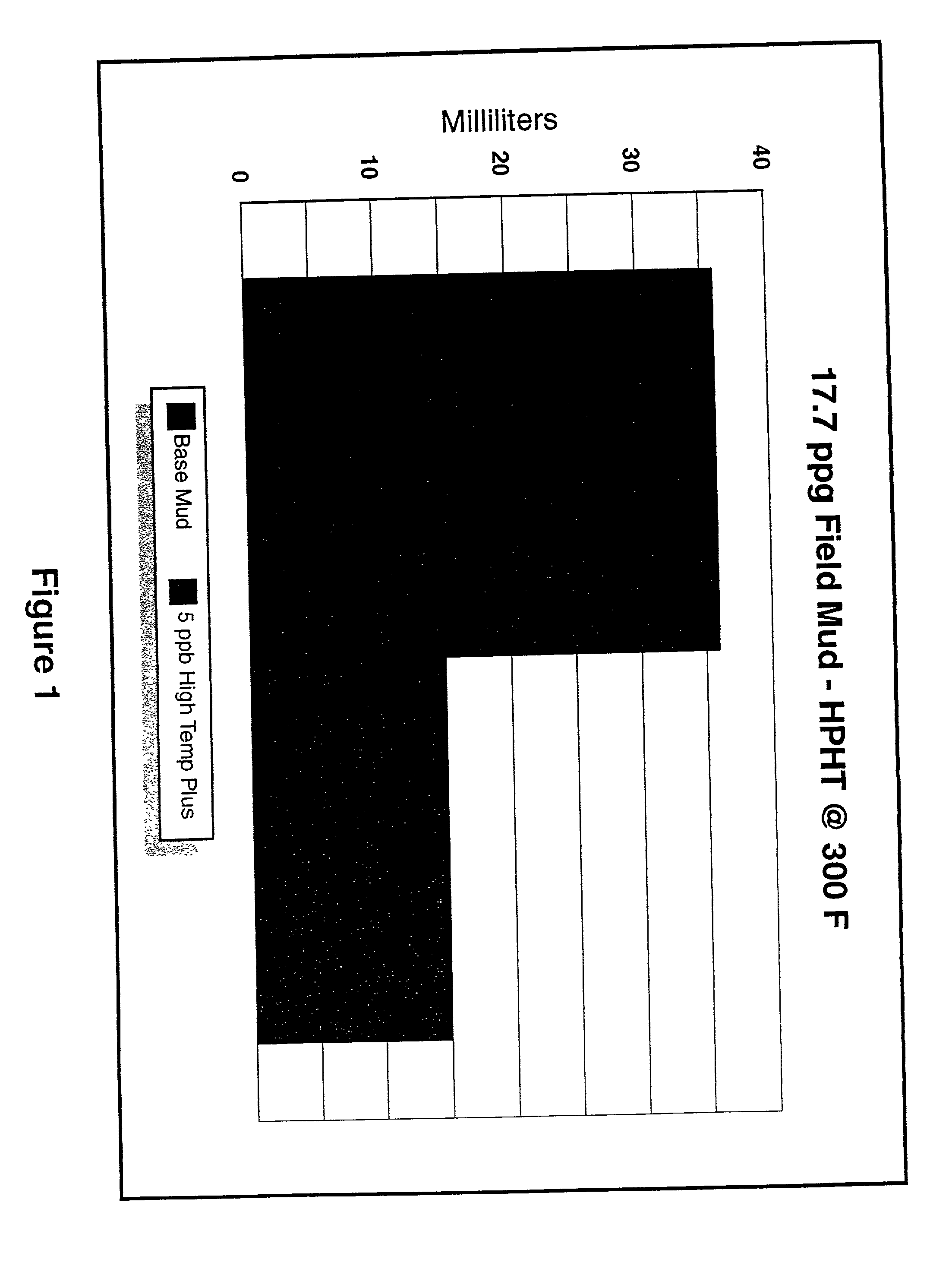
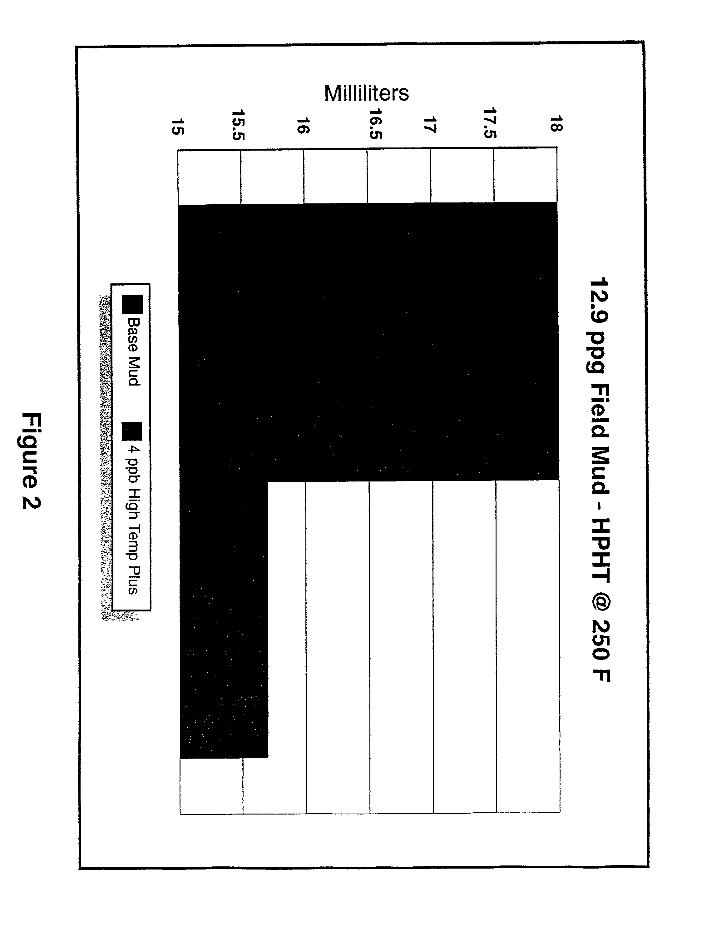
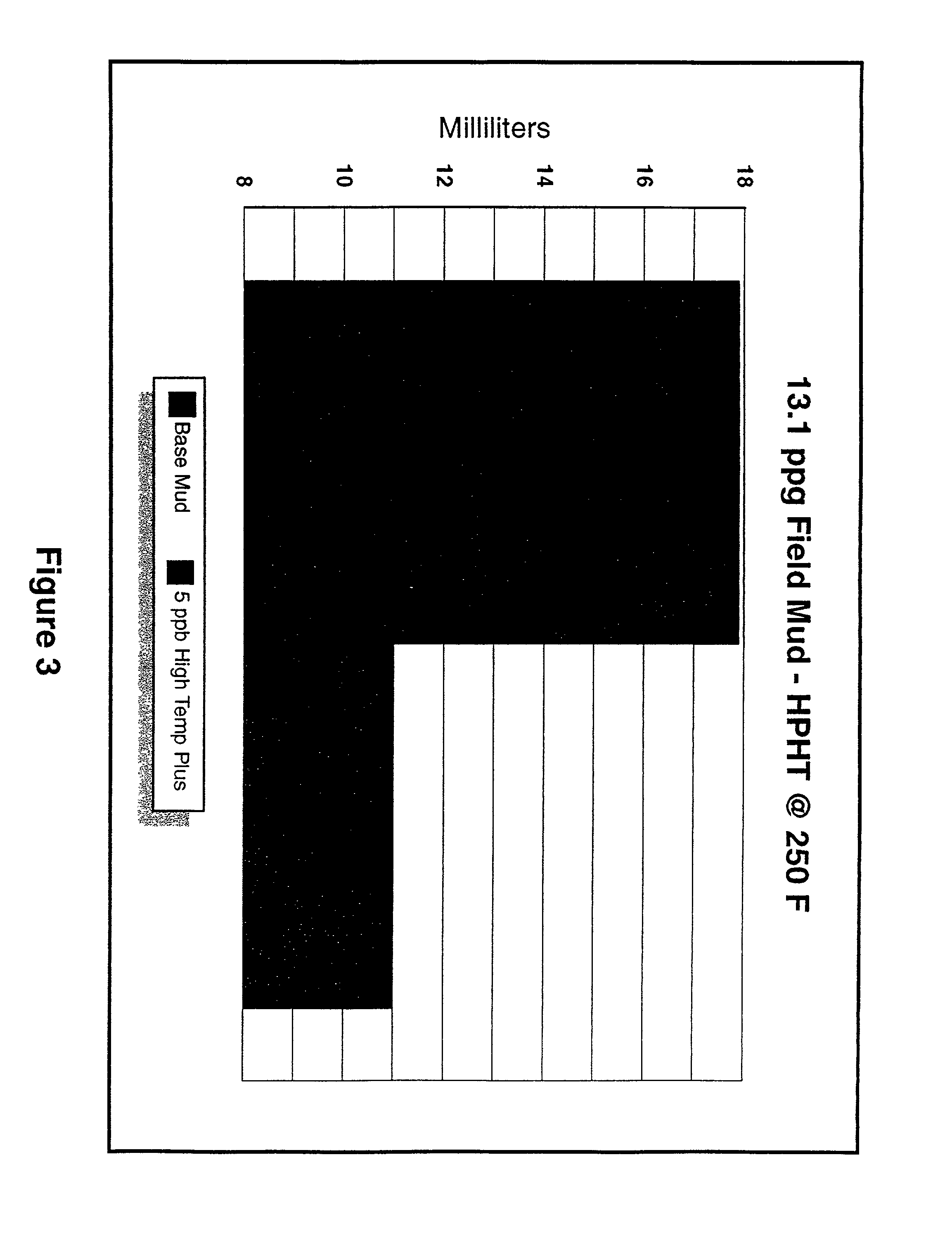
[0069] "HTHP" relates to high temperature high pressure fluid losses measured at 200-350.degree. F. / 500 psi differential and reported as ml / 30 min.

[0070] Using the viscometer described in API Bulletin RP 13B-1, the viscosity of the mud is determined b...


PUM


Abstract

The invention relates to a composition comprising an HPHT fluid loss control aid, stable at elevated temperatures and which also acts as an excellent shale stabilizer, bore hold lubricant, sealant for depleted sand, and wall cake conditioner. The HPHT fluid loss control aid broadly comprises a uintaite sold under the trade name Gilsonite(R), which also contains a surfactant such as a nonionic surfactant. The HPHT fluid loss control aid also contains a solubilized lignite such as causticized lignite and carbon black. The fluid loss control aid reduces HPHT filtrate loss, has good stability at elevated temperatures such as at 300° F., stabilizes troublesome shales and decreases bore hole erosion, helps seal depleted sands, reduces torque and drag, causes no adverse effects on the flow properties of the properly conditioned drilling fluid, and lowers total well costs.

Description

[0001] This application is based on provisional patent application U.S. Ser. No. 60 / 106,091 filed on Oct. 29, 1998.[0002] The field of the invention comprised an additive to reduce HPHT fluid loss in drilling fluids used in drilling subterranean wells.[0003] Drilling fluids, sometimes referred to as drilling muds, are complex mixtures of chemicals employed in drilling subterranean wells and perform a variety of functions. These drilling fluids generally comprise a liquid or slurry pumped down the down the drill string which exits through openings in the drill bit immediately adjacent the penetrated formation. The drilling fluid then flows upwardly in the annulus between the frill string and the wall of the hole to the surface and functions in a variety of ways. The drilling fluid both cools and lubricates the drill bit and because injected into the hole under pressure delivers power to te frill bit, carries cuttings upwardly out of the drill hole during circulation, suspends cutting...

Claims


Application Information

Patent Timeline
IPC IPC(8): C09K8/03C09K8/16
CPCC09K8/032C09K8/16
Inventor CRAWFORD, DONALD
Owner SUN DRILLING PRODS
Why Eureka
Try Eureka