
Safety Scanner

a scanner and safety technology, applied in the field of safety scanners, can solve the problems of affecting the optical performance, requiring maintenance of the optical rotator and the like, and requiring the replacement of the protective cover, so as to reduce the focus shift, uniform optical performance, and uniform optical performance

Inactive Publication Date: 2017-08-24
KEYENCE
View PDF5 Cites 7 Cited by
  • Summary
  • Abstract
  • Description
  • Claims
  • Application Information

AI Technical Summary

Benefits of technology

The invention aims to provide a safety scanner that can optically scan 180 degrees or more without being bulky or requiring a larger casing. The scanner includes a protective cover that can be easily attached to the casing and still achieve consistent performance.

Problems solved by technology

Further, maintenance of the optical rotator and the like is required or the protective cover is required to be replaced when damaged.
Thus, the curvature of the protective cover differs between the front side and the rear side with respect to the rotation axis, which disadvantageously changes the optical performance depending on a scanning angle of detection light.

Method used


Image

  • Safety Scanner
  • Safety Scanner
  • Safety Scanner

Examples


Embodiment Construction

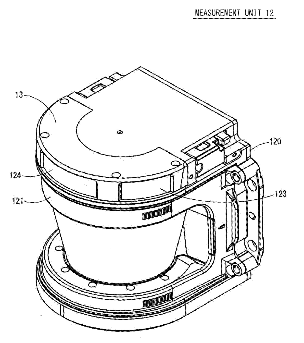
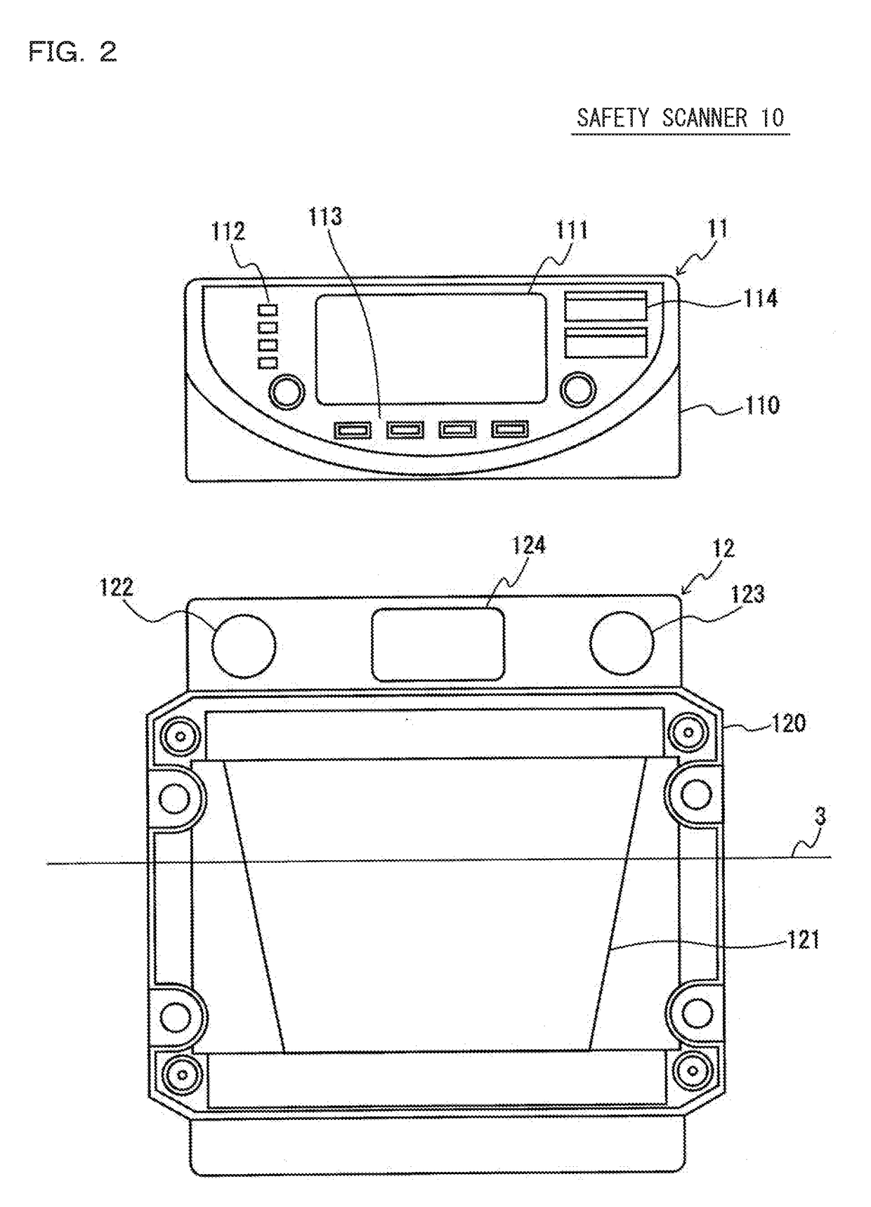
[0044]Hereinbelow, an embodiment of the present invention will be described with reference to the drawings. Although, in the present specification, a direction of a rotation axis of an optical rotator is described as an up-down direction (vertical direction) for convenience, the posture of a safety scanner according to the present invention when used is not limited by the described direction. First, a schematic configuration of an optical safety system as a premise of the present invention will be described below with reference to FIGS. 1 to 3.

1>

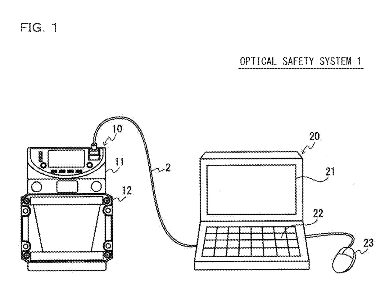
[0045]FIG. 1 is a system diagram illustrating a configuration example of an optical safety system 1 which includes a safety scanner 10 according to an embodiment of the present invention. The optical safety system 1 includes the safety scanner 10 which senses an intruder within a protection area and outputs a sensing signal, and a setting support device 20 which generates setting data for the safety scanner. The safety scanner 10 and the set...


PUM


Abstract

Provided is a safety scanner capable of obtaining uniform optical performance for a view angle of 180° or more. The safety scanner includes an optical rotator that emits detection light from a light source to a detection area and causes the detection light to perform scanning in a circumferential direction, a light receiving element that receives reflected light from an object within the detection area through the optical rotator, a casing that houses the light receiving element. The casing includes a canopy part, a bottom part facing the canopy part, and a coupling part that couples a rear end of the canopy part to a rear end of the bottom part. The protective cover includes a window formed in a circular arc shape, corresponding to an optical path of the detection light and the reflected light, having a central angle larger than 180° with respect to the rotation axis.

Description

CROSS-REFERENCE TO RELATED APPLICATIONS[0001]The present application claims foreign priority based on Japanese Patent Application No. 2016-031507, filed Feb. 22, 2016, the contents of which is incorporated herein by reference.BACKGROUND OF THE INVENTION[0002]1. Field of the Invention[0003]The present invention relates to a safety scanner, and more particularly, to an improvement of a safety scanner that optically senses an intruder into a protection area.[0004]2. Description of Related Art[0005]An optical safety sensor is an area monitoring device which optically senses an intruder such as a person intruded into a protection area and outputs a safety control signal for emergently stopping a machine such as a machine tool or an industrial robot (e.g., JP 2009-296087 A and JP 2009-294734 A).[0006]For example, a safety scanner is an optical scanning area monitoring device provided with an optical rotator which emits detection light from a light source to a detection area and causes the...

Claims


Application Information

Patent Timeline
Patent Type & Authority Applications(United States)
IPC IPC(8): G01S7/481G08B13/24G01S17/42
CPCG01S7/4813G08B13/2491G01S7/4817G01S17/42G08B13/187G08B13/19619G08B29/183
Inventor OH, CHORYON
Owner KEYENCE
Learn More