Method and apparatus for continuously stretching polymer films

Inactive Publication Date: 2009-06-18
FUJIFILM CORP
View PDF4 Cites 3 Cited by
  • Summary
  • Abstract
  • Description
  • Claims
  • Application Information

AI Technical Summary

Benefits of technology

[0015]In the present invention, the welding process is adequately performed to the overlapped portion where a front end and a rear end of two films are overlapped. By splicing the two films into one film, stretching process is continuously applied under the identical conditions to the spliced film while the conveyance failure and rupture of the spliced film are prevented. Therefore, according to the present invention, the stretching process is efficiently preformed in the off-line stretching apparatus. Thus, a film having excellent surface conditions and uniform optical properties without slacks and wrinkles is efficiently produced.

Problems solved by technology

However, it is difficult to adjust thickness accuracy of the film, and fine streaks (die lines) appear on the film.
Accordingly, the melt-extrusion method is not suitable for the production of the optical film.
However, such high-speed drying causes unevenness in drying which results in surface defects on the film.
Although the cooling gelation method is adopted to increase the production efficiency, substantial increase cannot be achieved since the film conveying speed in the clip tenter is slower than the support moving speed.
When such film is stretched, the film may be ruptured from a portion having the thickness unevenness.
As a result, convey failure and / or film rupture may occur.

Method used


Image

  • Method and apparatus for continuously stretching polymer films
  • Method and apparatus for continuously stretching polymer films
  • Method and apparatus for continuously stretching polymer films

Examples


Embodiment Construction

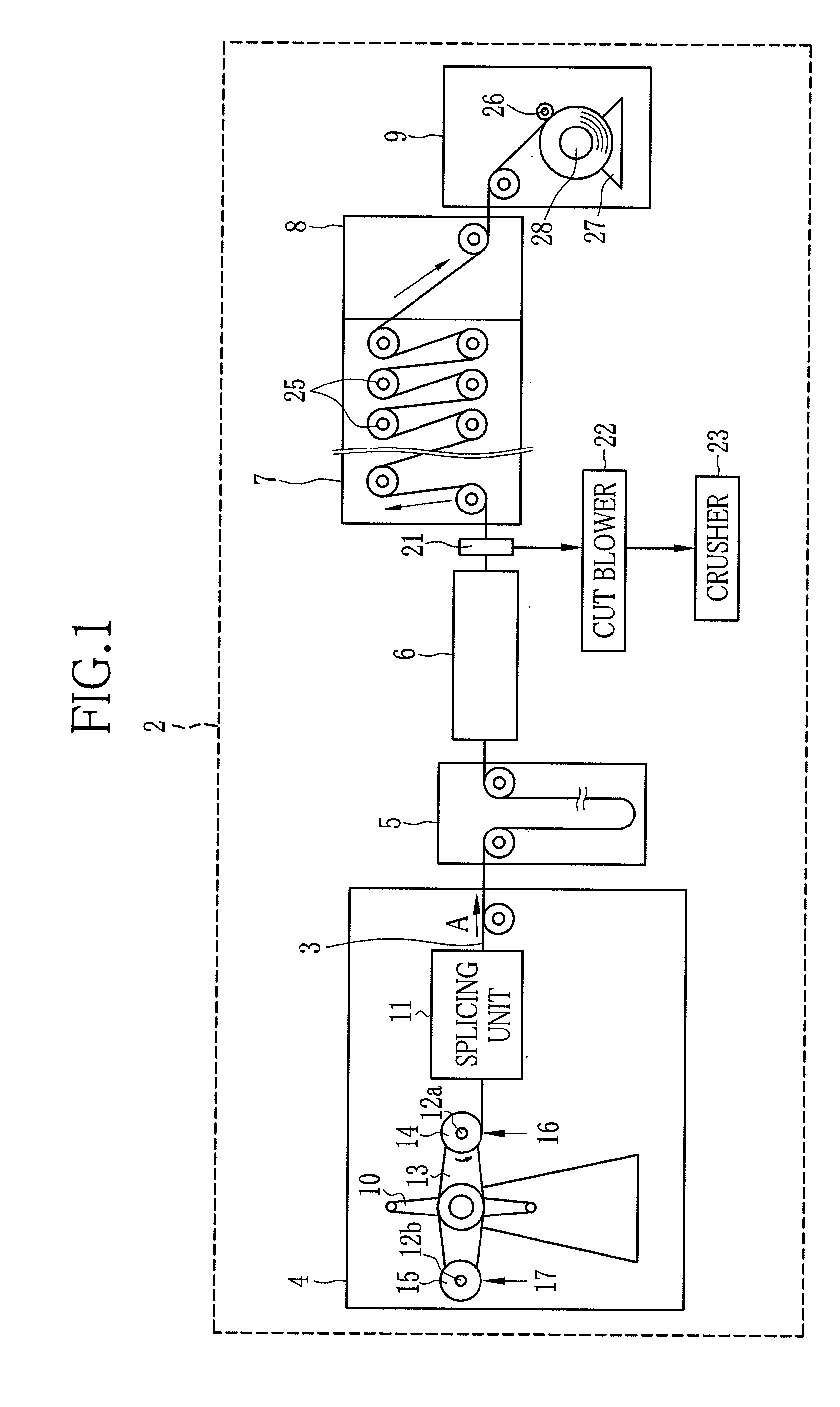
[0029]As shown in FIG. 1, an off-line stretching device 2 is provided with a film supply chamber 4 for supplying a film 3, a reservoir 5, a tenter section 6, a heat relaxation chamber 7, a cooling chamber 8, and a winding chamber 9 in this order. In the tenter section 6, the film 3 is stretched continuously without interruption.

[0030]The film supply chamber 4 is provided with a turret-type film feeding device 10 and a splicing unit 11. The film feeding device 10 has a turret arm 13. The ends of the turret arm 13 are provided with mounting shafts 12a and 12b respectively. The mounting shaft 12a is loaded with a film roll 14. The turret arm 13 is rotated by 180° (degrees) at a time to set the mounting shaft 12a in a film feeding position 16, which sets the other mounting shaft 12b in a film replacement position 17. Thus, the film roll 14 is set in the film feeding position 16.

[0031]The film feeding device 10 feeds the film 3 from the film roll 14 to the splicing unit 11. A core of the...


PUM

PropertyMeasurementUnit
Lengthaaaaaaaaaa
Lengthaaaaaaaaaa
Temperatureaaaaaaaaaa

Abstract

A rear end of a preceding film and a front end of a trailing film are overlapped with an overlap length Lo. Each of a pair of welding heads has a contact surface and a film heating surface. The contact surface has a length Lp in a conveying direction. The film heating surface has a length Lh in the conveying direction. The lengths Lh, Lo, and Lp satisfy Lh<Lo<Lp. Center portions of an overlapped portion, the contact surface, and the heat surface are approximately aligned with each other in the conveying direction. The overlapped portion is sandwiched by the welding heads in an overlapping direction C. The overlapped portion is welded through the film heating surfaces such that temperatures of the films at both ends of each contact surface in the conveying direction are heated to a temperature at which the films are welded.

Description

FIELD OF THE INVENTION[0001]The present invention relates to a method and an apparatus for continuously stretching spliced polymer films.BACKGROUND OF THE INVENTION[0002]A polymer film (hereinafter referred to as film) has advantages such as excellent light transmission properties and flexibility, and is easy to be made lighter and thinner. Accordingly, the film is widely used as an optical functional film. TAC film formed of cellulose acylate, in particular, cellulose triacetate (TAC) with an average acetylation degree in a range from 57.5 to 62.5% has toughness and flame retardancy, and therefore the TAC film is utilized as a film base for photosensitive material. Additionally, since the TAC film has optical isotropy superior to other polymer films, the TAC film is utilized as an optical film such as a protective film for a polarizing filter, an optical compensation film, for example, a wideview film, in an LCD and the like.[0003]As a film production method, mainly, there are a me...

Claims


Application Information

Patent Timeline
IPC IPC(8): B32B37/04B32B37/00
CPCB29C41/26B29C66/919B29C47/367B29C47/68B29C47/686B29C47/8845B29C47/906B29C55/08B29C55/20B29C65/18B29C65/38B29C66/1122B29C66/344B29C66/3472B29C66/43B29C66/91421B29C66/9192B29K2001/00B29K2001/12B29K2101/12B29K2105/0079B29K2905/02B29K2995/0013B29L2031/3475B65H19/1852B65H2301/4621B65H2301/4634B65H2301/51242B65H2515/40B65H2701/1752B29C47/0021B29C66/91645B29C65/305B29C66/91431B29C66/8181B65H2220/02B29C66/83221B29K2995/007B29C66/81264B29C66/0044B29C66/8122B29C66/81831B29C66/71B29C48/08B29C48/387B29C48/69B29C48/693B29C48/91B29C48/914B29C48/906B29C66/853B29K2827/18
Inventor AOSHIMA, SHINSUKETAKAHASHI, MISAO
Owner FUJIFILM CORP
Why Eureka
Try Eureka