
Interlocking intramedullary rod assembly for treating proximal tibial fractures

a technology of proximal tibial fracture and interlocking rod, which is applied in the direction of internal osteosynthesis, internal osteosynthesis, osteosynthesis devices, etc., can solve the problems of inability to achieve proper support for the fracture site, inability to control the motion of the first generation of intramedullary rods, and more complex surgical procedures

Inactive Publication Date: 2017-09-07
NAIL KINETICS LLC
View PDF3 Cites 4 Cited by
  • Summary
  • Abstract
  • Description
  • Claims
  • Application Information

AI Technical Summary

Benefits of technology

The patent describes a new way to fix bones that are broken. It allows the surgeon to secure two parts of the bone together with a special rod, using two different types of fixation: a fixed position and an adjustable position. The rod can also be moved to change the way the bones are positioned and how much they are compressed. This invention allows for more precise and flexible fixation of bones, which can help improve the recovery process for patients.

Problems solved by technology

However, the use of an intramedullary rod also involves a more complex surgical procedure and higher cost.
However, it can sometimes be difficult to achieve proper support for the fracture site with plates upon the application of weight.
The first generation of intramedullary rods does not control motion at the fracture line in any specific plane.
However, with current interlocking intramedullary rods, the surgeon cannot easily adjust the disposition of one of the bone fragments (e.g., the proximal bone fragment) relative to the other of the bone fragments (e.g., the distal bone fragment).
This makes it challenging for the surgeon to align the two bone fragments relative to one another in an optimal manner.
As this occurs, one of the bone fragments may become misaligned relative to the other of the bone fragments, so that it is secured to the interlocking intramedullary rod in a non-optimal manner.

Method used


Image

  • Interlocking intramedullary rod assembly for treating proximal tibial fractures
  • Interlocking intramedullary rod assembly for treating proximal tibial fractures
  • Interlocking intramedullary rod assembly for treating proximal tibial fractures

Examples


Embodiment Construction

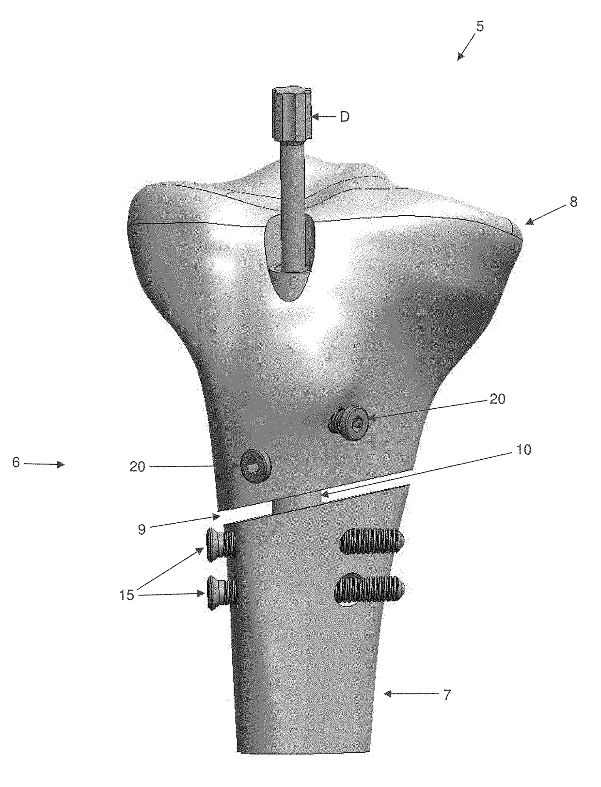
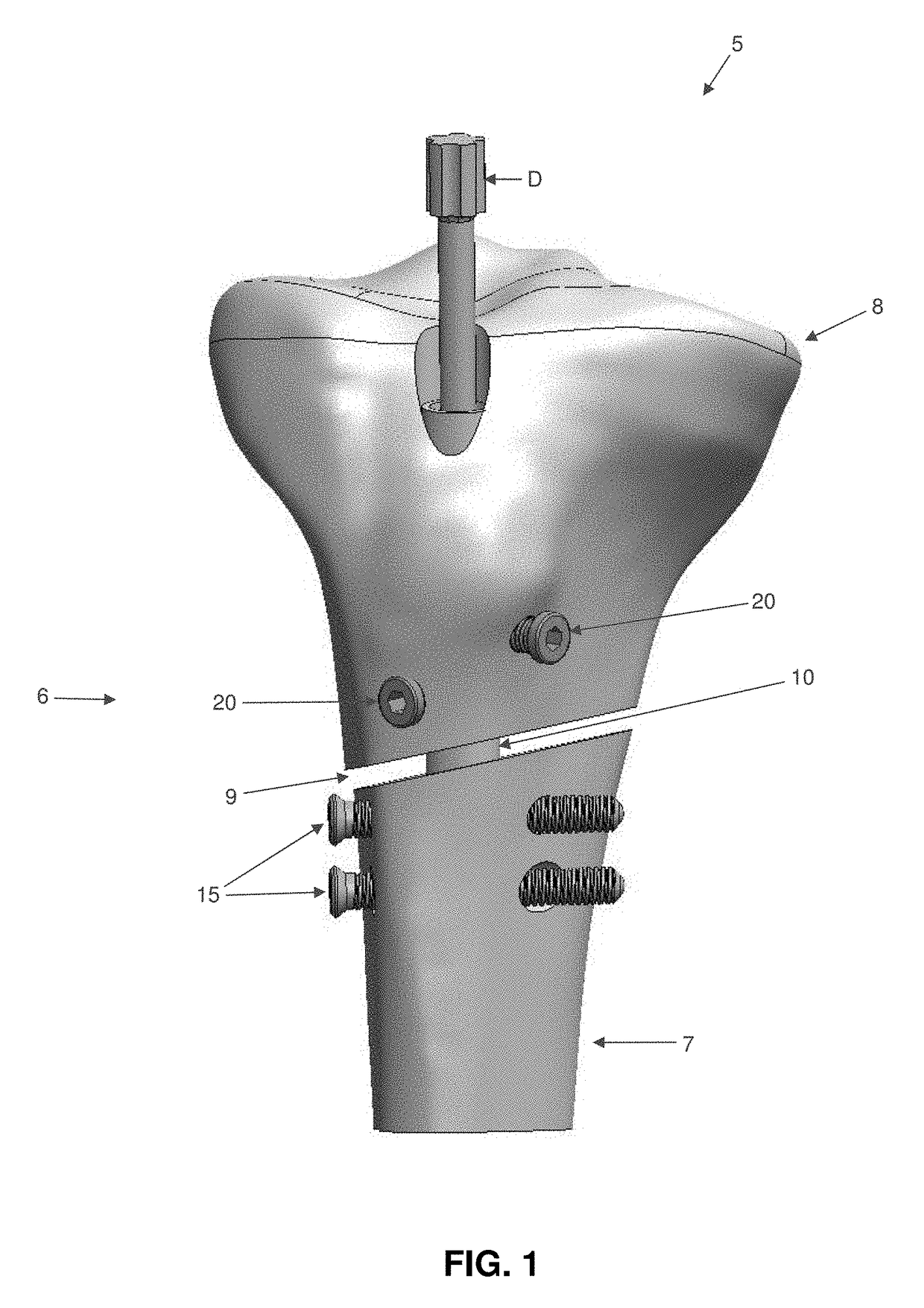
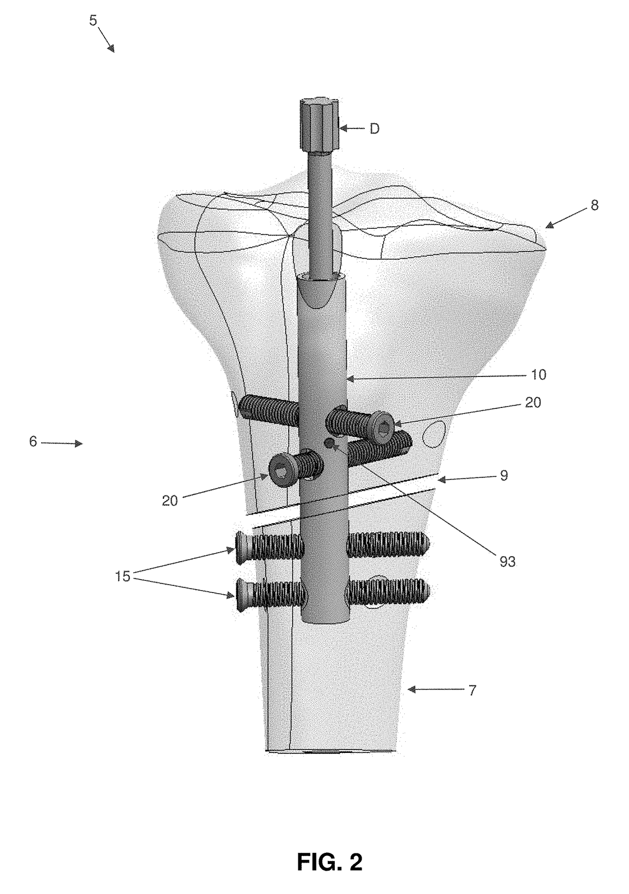
[0044]The present invention comprises the provision and use of a novel interlocking intramedullary rod assembly which allows the surgeon to (i) secure a first bone fragment of a fractured bone (e.g., a distal bone fragment) to the interlocking intramedullary rod assembly in a fixed position, (ii) secure a second bone fragment of the fractured bone (e.g., a proximal bone fragment) to the interlocking intramedullary rod assembly in an adjustable manner, and (iii) thereafter selectively pivot the second bone fragment (e.g., the proximal bone fragment) relative to the first bone fragment (e.g., the distal bone fragment) so as to secure the two bone fragments in position relative to one another with the desired orientation and / or with the desired degree of compression.

Novel Interlocking Intramedullary Rod Assembly

[0045]Looking first at FIGS. 1-3, there is shown a novel interlocking intramedullary rod assembly 5 formed in accordance with the present invention. Novel interlocking intramedu...


PUM


Abstract

A novel interlocking intramedullary rod assembly which allows the surgeon to (i) secure a first bone fragment of a fractured bone (e.g., a distal bone fragment) to the interlocking intramedullary rod assembly in a fixed position, (ii) secure a second bone fragment of the fractured bone (e.g., a proximal bone fragment) to the interlocking intramedullary rod assembly in an adjustable manner, and (iii) thereafter selectively pivot the second bone fragment (e.g., the proximal bone fragment) relative to the first bone fragment (e.g., the distal bone fragment) so as to secure the two bone fragments in position relative to one another with the desired orientation.

Description

FIELD OF THE INVENTION[0001]This invention relates generally to an interlocking intramedullary rod assembly for treating fractures of a long bone, and more particularly to an interlocking intramedullary rod assembly for treating fractures of the tibia.BACKGROUND OF THE INVENTION[0002]Fractures of the tibia are traditionally treated with either (i) an intramedullary rod (sometimes referred to as an intramedullary nail) which is positioned in the intramedullary canal of the tibia, or (ii) a plate applied to the side of the tibia and fixed in place with screws set into the tibia. The choice of using an intramedullary rod or a plate is generally based on the location and complexity of the fracture.[0003]As noted above, the intramedullary rod is placed in the intramedullary canal of the tibia and typically provides excellent mechanical stability for the bone. Among other things, the intramedullary rod exhibits good weight-sharing properties. However, the use of an intramedullary rod also...

Claims


Application Information

Patent Timeline
IPC IPC(8): A61B17/72
CPCA61B17/7241A61B17/725A61B17/7225A61B17/74A61B2017/681
Inventor BORAIAH, SREEVATHSASZATKOWSKI, JAN PAUL
Owner NAIL KINETICS LLC
Learn More