Electrical drive system for an aircraft and operating method

a technology of electric drive system and aircraft, applied in the direction of electric device, battery/fuel cell control arrangement, light to electrical conversion, etc., can solve the problems of reducing the redundancy cost and accepting a very large weight, and achieve the effect of improving redundancy and saving weight and cos

Active Publication Date: 2017-09-07
AIRBUS DEFENCE & SPACE +1
View PDF10 Cites 23 Cited by
  • Summary
  • Abstract
  • Description
  • Claims
  • Application Information

AI Technical Summary

Benefits of technology

[0011]An aspect of the invention relates to improving an electrical drive system for aircraft in such a way that an advantageous utilization of different sources of energy is made possible while improving the redundancy and, at the same time, saving weight and cost.

Problems solved by technology

This results in the need to accept a very large weight and also a cost disadvantage for providing the required redundancy as a safety buffer against the failure of a drive component.

Method used


Image

  • Electrical drive system for an aircraft and operating method
  • Electrical drive system for an aircraft and operating method
  • Electrical drive system for an aircraft and operating method

Examples


Embodiment Construction

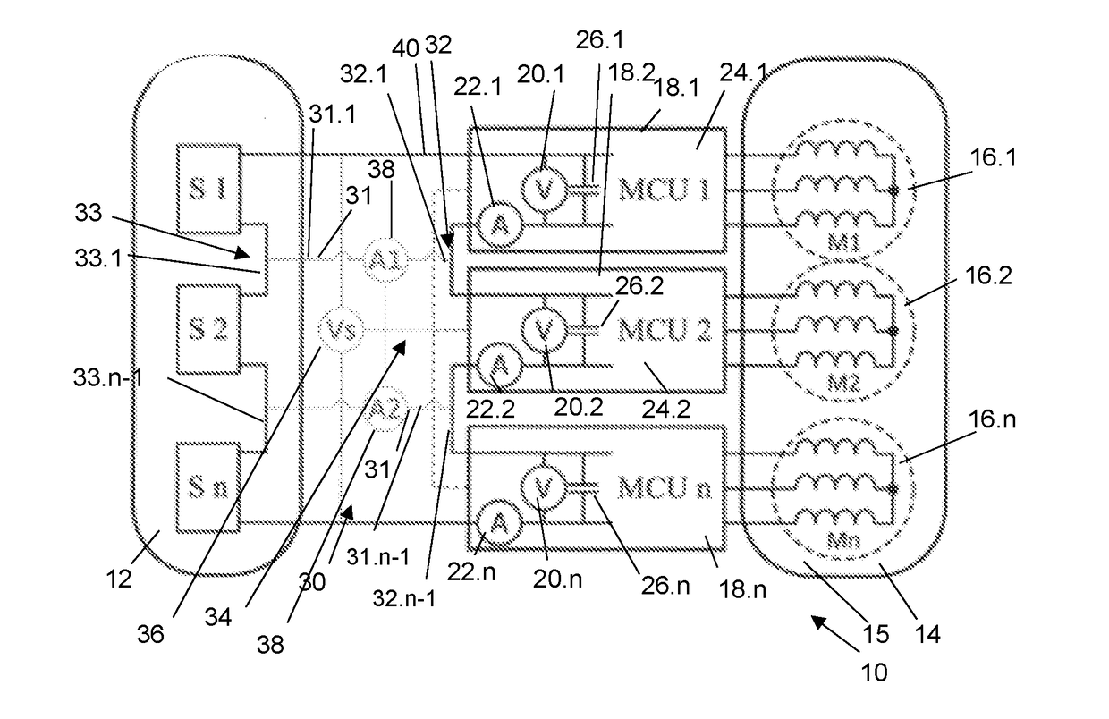
[0057]FIG. 1 shows a schematic block diagram of a first embodiment of an electrical drive system 10 for an aircraft.

[0058]The drive system 10 has a modular energy source 12 and a modular motor 14.

[0059]The modular motor 14 is one example of a modular electrical machine 15.

[0060]The modular energy source 12 has several electrical direct voltage sources S1, S2, . . . , Sn, wherein n≧2. The illustrated general block diagram shows a first direct voltage source S1 and a second direct voltage source S2 and another direct voltage source Sn.

[0061]The modular motor has several motor modules M1, M2, . . . , Mn, wherein n≧2. The motor modules M1, M2, . . . , Mn are examples of electrical machine module 16.1, 16.2, 16.n forming a module of the electrical machine 15 which, in a configuration as electrical motor modules or in a motor mode, are able to convert electrical energy into mechanical movement and, in a configuration as generator modules or in a generator mode, are able to convert mechani...


PUM


Abstract

An electrical drive system for an aircraft includes: at least one first and one second electrical direct voltage sources for supplying a direct voltage, and a first and a second electrical machine modules configured to convert electrical alternating voltage into mechanical movement and vice versa. The first and second modules are connected to a first and a second power inverters, respectively. The first and second inverters are connected in series and the first and the second direct voltage sources are connected in series to generate an overall direct voltage to which the inverters are connected. The power inverters each has one voltage measuring device for measuring the power inverter direct voltage present at the respective inverter and a power inverter control device for controlling the operation of the inverters in accordance with the power inverter direct voltage.

Description

FIELD OF THE INVENTION[0001]The invention relates to an electrical drive system for an aircraft. The invention further relates to an aircraft having such an electrical drive system and a method for operating such an electrical drive system.BACKGROUND OF THE INVENTION[0002]The testing of novel and alternative drive concepts for the propulsion or for ancillary components of aircraft is one subject matter of current research in the aviation sector. The propulsive drive system of the Airbus E-Fan is one example for an electrical drive system for aircraft; see https: / / de.wikipedia.org / wiki / airbus_e-fan, version of 12 Feb. 2016. The Airbus E-Fan is a two-seater electric aircraft by Airbus Group Innovations and serves for testing novel drive concepts. It is driven by two ducted propellers with a variable pitch that are respectively driven by electric motors. Lithium-ion batteries are accommodated in the wings for storing energy.[0003]Efforts are being made to also use other electrical ener...

Claims


Application Information

Patent Timeline
Patent Type & Authority Applications(United States)
IPC IPC(8): B64D41/00H02P27/06B64D27/24B60L50/15
CPCB64D41/00H02P27/06B64D27/24B60L1/003B60L3/0092B60L8/003B60L9/22B60L9/30B60L15/007B60L15/32B60L15/38B60L2200/10B60L2210/42B60L50/90B60L50/15B60L50/51B60L58/18B60L58/19B60L58/20B60L50/66Y02T10/70Y02T10/7072Y02T10/72
Inventor WANGEMANN, JOERGSCHULT, JENS
Owner AIRBUS DEFENCE & SPACE
Why Eureka
Try Eureka