Heat transfer plate and plate heat exchanger

a technology of heat exchanger and heat transfer plate, which is applied in the direction of lighting and heating apparatus, stationary conduit assemblies, laminated elements, etc., can solve the problems of increasing the total weight and the overall cost of the heat exchanger, and achieve the effect of reducing the stress on the heat transfer plate inside the casing and reducing the thickness of the cover

Active Publication Date: 2017-09-07
ALFA LAVAL CORP AB +1
View PDF1 Cites 7 Cited by
  • Summary
  • Abstract
  • Description
  • Claims
  • Application Information

AI Technical Summary

Benefits of technology

[0034]This is advantageous in that nozzle loads are supported by the covers, which significantly reduces the stress on the heat transfer plate

Problems solved by technology

However, in some applications the casing has to be relatively thick to be able to handle the desired

Method used


Image

  • Heat transfer plate and plate heat exchanger
  • Heat transfer plate and plate heat exchanger
  • Heat transfer plate and plate heat exchanger

Examples


Embodiment Construction

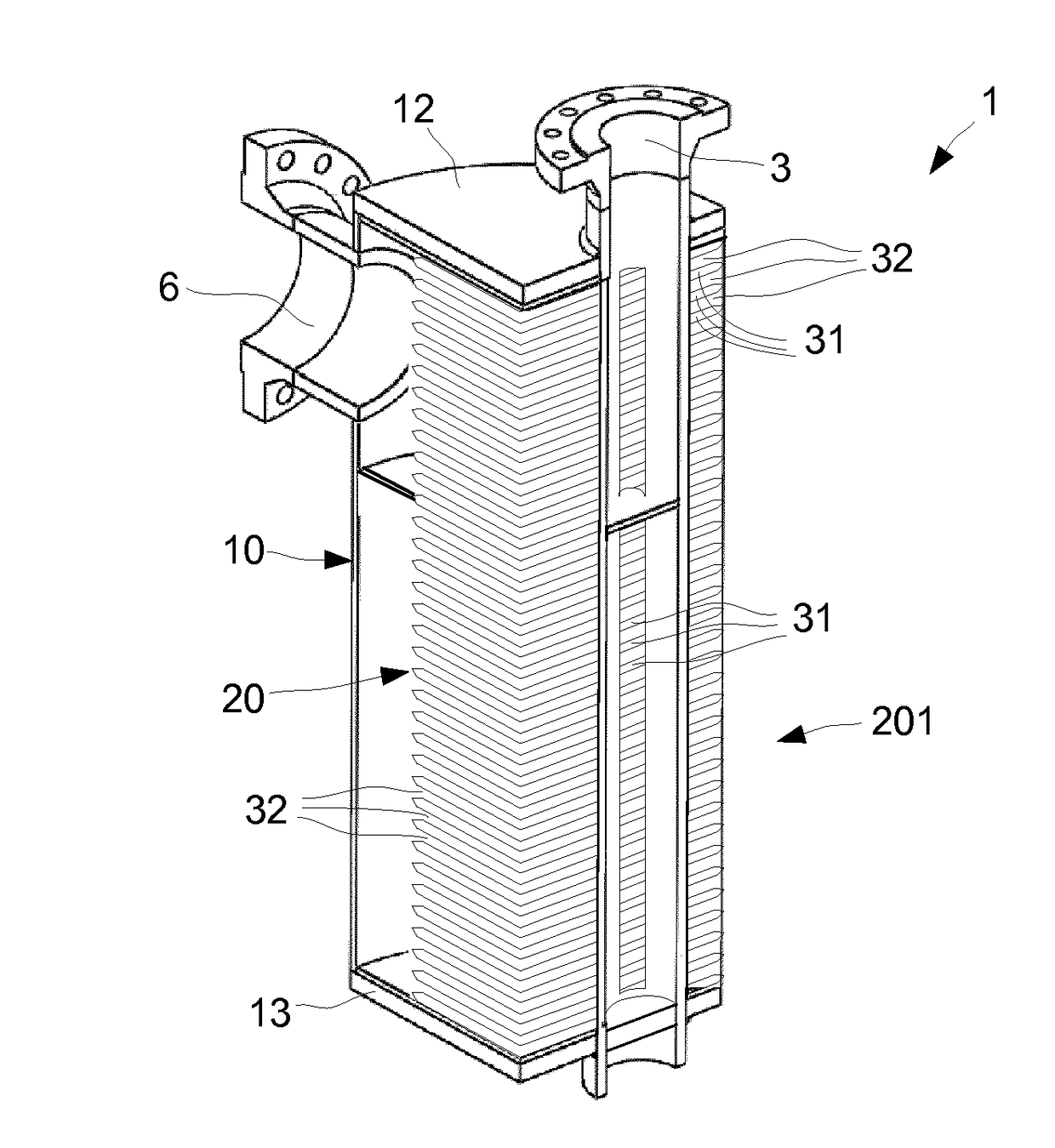
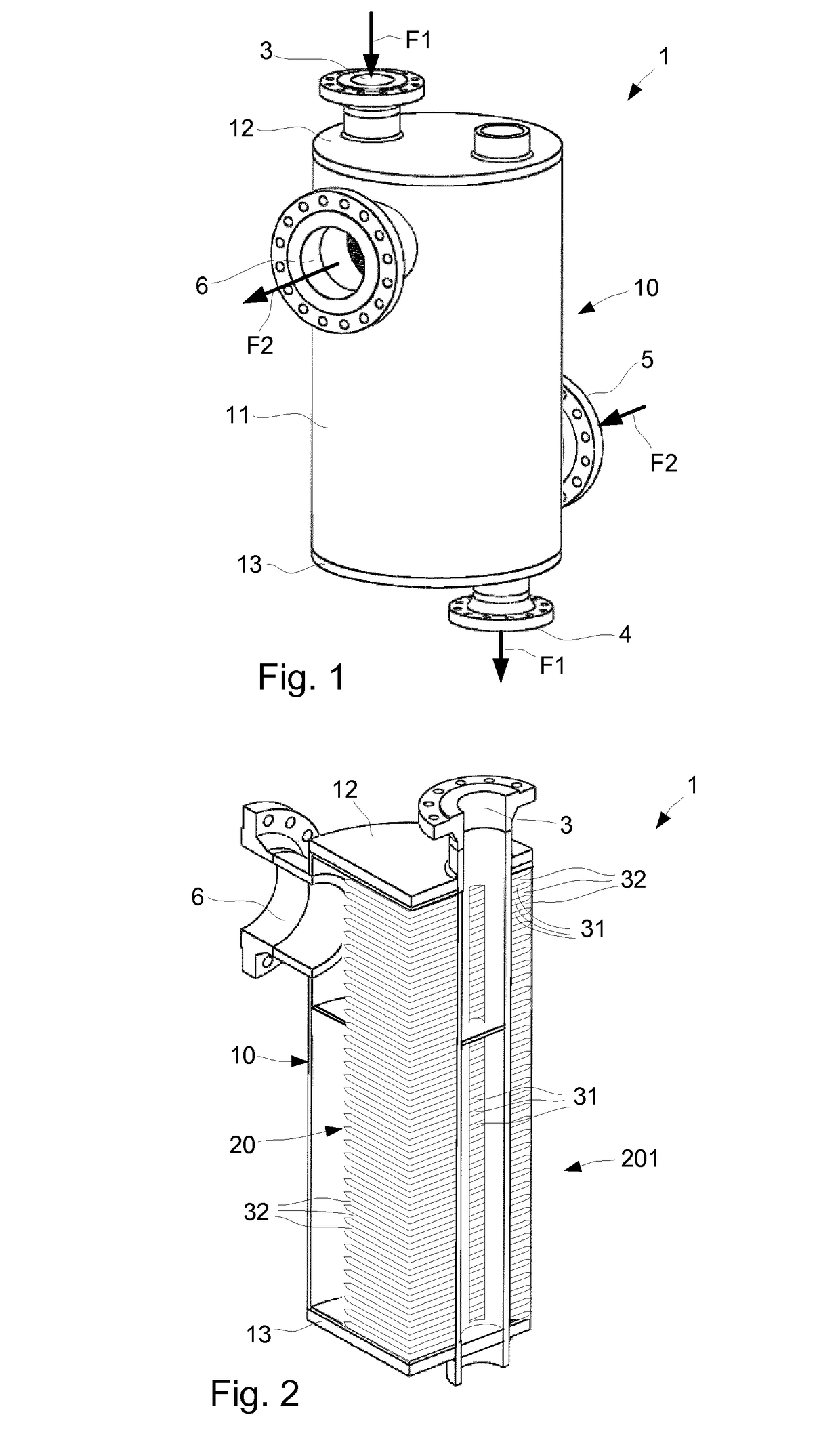
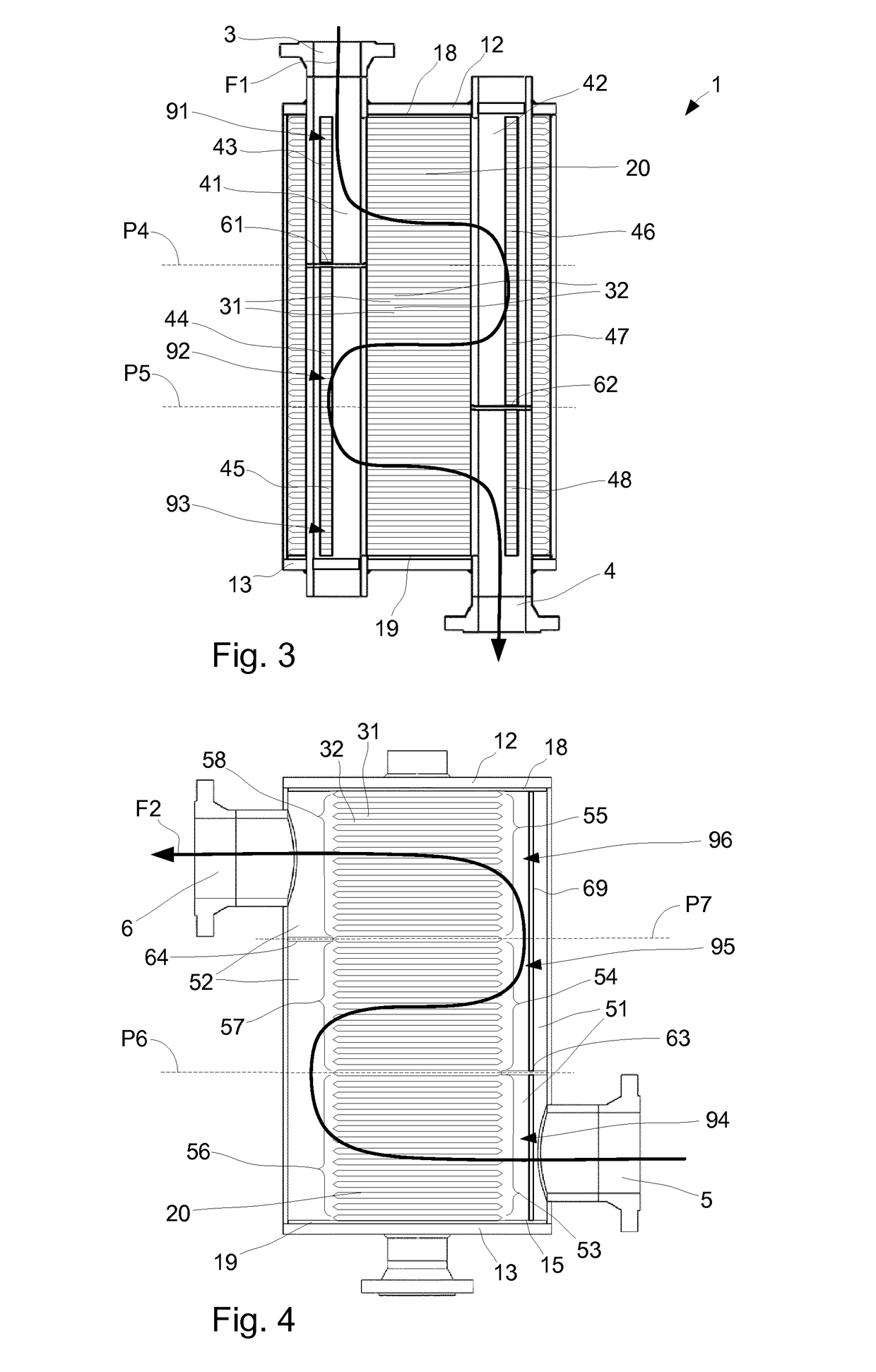
[0053]With reference to FIGS. 1 and 2 a plate heat exchanger 1 is illustrated. All illustrated parts of the plate heat exchanger 1 are generally made of metal. Some parts like conventional gaskets may be made of other materials. The plate heat exchanger 1 has a casing 10 in the form of a cylindrical casing 11 that is sealed by a top cover 12 and a bottom cover 13, such that a sealed enclosure is formed within the casing 10. The plate heat exchanger 1 has in the top cover 12 a first heat exchanger inlet 3 for a first fluid F1 and has in the bottom cover 13 a first heat exchanger outlet 4 for the first fluid F1. A second heat exchanger inlet 5 for a second fluid F2 is arranged in the cylindrical casing 11, at an end of the cylindrical casing 11 that is proximate the bottom cover 13. A second heat exchanger outlet 6 for the second fluid F2 is arranged in the cylindrical casing 11, at an end of the cylindrical casing 11 that is proximate the top cover 12. Each of the inlets 3, 5 and out...


PUM


Abstract

A heat transfer plate comprising a first port opening and a second port opening for allowing a first fluid to flow over a top surface of the heat transfer plate, a first side opening and an opposite, second side opening for allowing a second fluid to flow over a bottom surface of the heat transfer plate, a number of rows of alternating tops and grooves that extend along the heat transfer plate, where a transition between a top and an adjacent groove is formed by an inclined portion, and plate portions that extend along the heat transfer plate, between the rows of tops and grooves, thereby forming flow channels between the rows of tops and grooves.

Description

TECHNICAL FIELD[0001]The invention relates to a heat transfer plate with a so called roller coaster pattern, which comprises a number of rows where each row has alternating tops and grooves that extend along a central plane of the heat transfer plate, between a top plane and a bottom plane of the heat transfer plate. The top plane and bottom plane are substantially parallel to the central plane and are located on a respective side of the central plane, where a transition between each top and adjacent groove in the same row is formed by a portion of the heat transfer plate that is inclined relative the central plane.BACKGROUND ART[0002]Today many different types of plate heat exchangers exist and are employed in various applications depending on their type. Some types of plate heat exchangers have a casing that forms a sealed enclosure in which heat transfer plates that are joined are arranged. The heat transfer plates form a stack of heat transfer plates where alternating first and ...

Claims


Application Information

Patent Timeline
IPC IPC(8): F28D9/00F28D1/03F28F3/02
CPCF28D9/005F28D9/0012F28F3/027F28D1/035F28F3/046F28D9/0006F28F3/044F28F3/02F28D1/02F28D9/0031F28D9/0043F28F2250/10
Inventor NOEL-BARON, OLIVIER
Owner ALFA LAVAL CORP AB
Why Eureka
Try Eureka