Solenoid - actuator with passive temperature compensation

a solenoid actuator and passive technology, applied in the field of magnetic coils, can solve the problems of high current, high cost, excessive heating of the coil, etc., and achieve the effects of reducing the number of coils, facilitating temperature compensation, and reducing the current flow

Inactive Publication Date: 2017-09-07
HANON SYST
View PDF0 Cites 1 Cited by
  • Summary
  • Abstract
  • Description
  • Claims
  • Application Information

AI Technical Summary

Benefits of technology

[0008]Overall, the behavior of an actuator provided with the magnetic coil and, in particular, the force provided can be made more uniform because the NTC behavior reduces the flowing current at comparatively low temperatures. As the temperature increases and the resistance of the compensation circuitry decreases, the resistance of the coil increases, so that a similar current continues to flow, and the provided force does not change appreciably.
[0022]Furthermore, several components can be used whose electrical resistance decreases with increasing temperature. These components can be connected in parallel, in series or in a mixture of a parallel and in series circuitry, and lead to the design margin also becoming larger. Similar to the above, this leads to the fact that standard components can be used, resulting in a cost reduction. For the same reasons, it is also possible to use several resistors with a constant resistance value for temperature increases and / or several components whose electrical resistance increases with temperature increases.

Problems solved by technology

This relates in particular to valves in the field of vehicle technology, which can be subject to extensive temperature fluctuations which also affect the actuators.
This has so far been compensated, for example, by using larger wire diameters for the coil, which leads to high currents even at comparatively low temperatures, which in turn can lead to excessive heating of the coil.
Other solutions use an auxiliary coil for temperature compensation (e.g., DE 19646986), but this is cost intensive.

Method used


Image

  • Solenoid - actuator with passive temperature compensation
  • Solenoid - actuator with passive temperature compensation
  • Solenoid - actuator with passive temperature compensation

Examples


Embodiment Construction

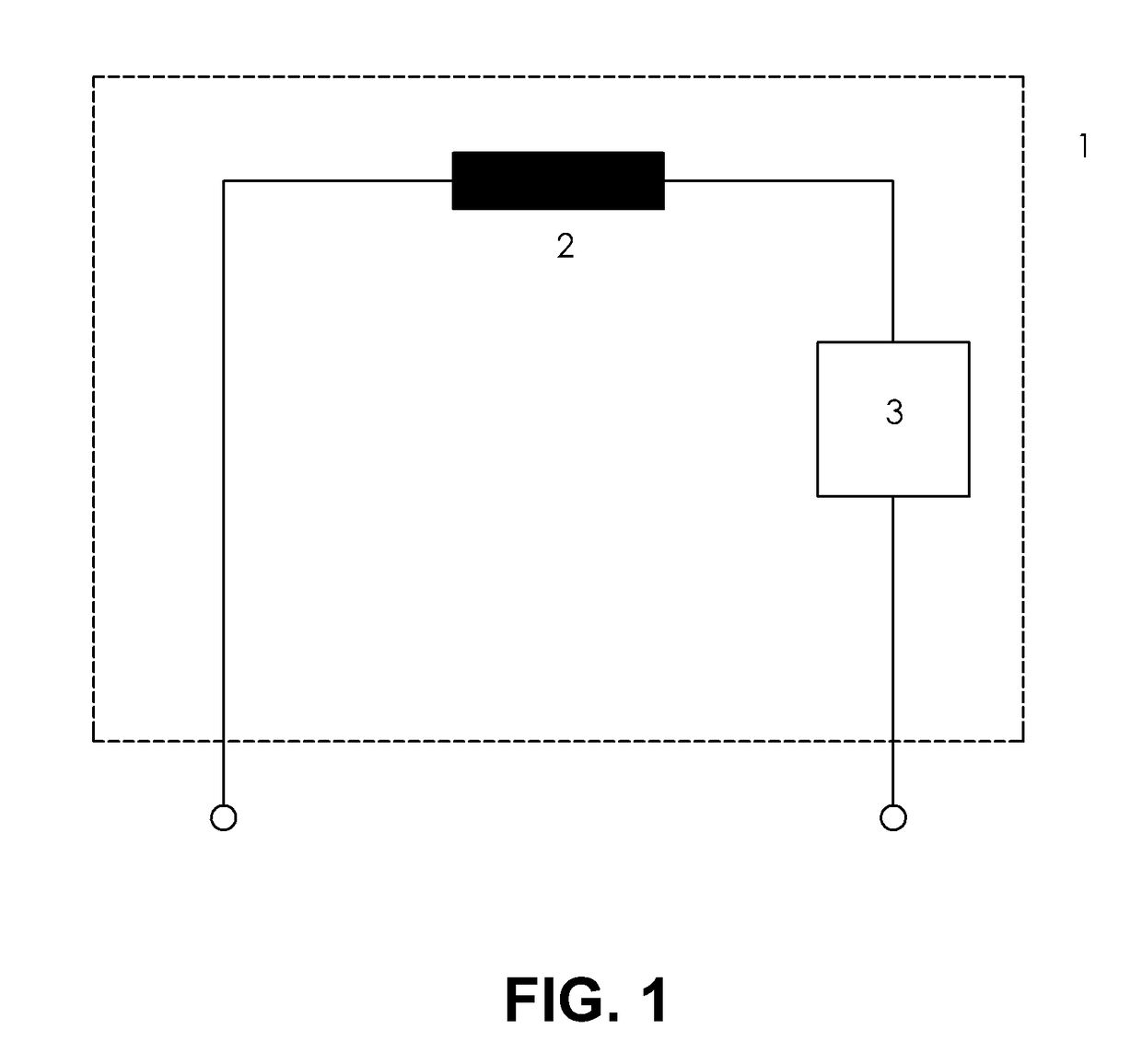
[0031]The magnetic coil 1 shown schematically in FIG. 1 has a coil 2 whose electrical resistance increases with increasing temperature. In order to compensate for this, a passive circuit 3 with NTC behavior is connected in series with the coil.

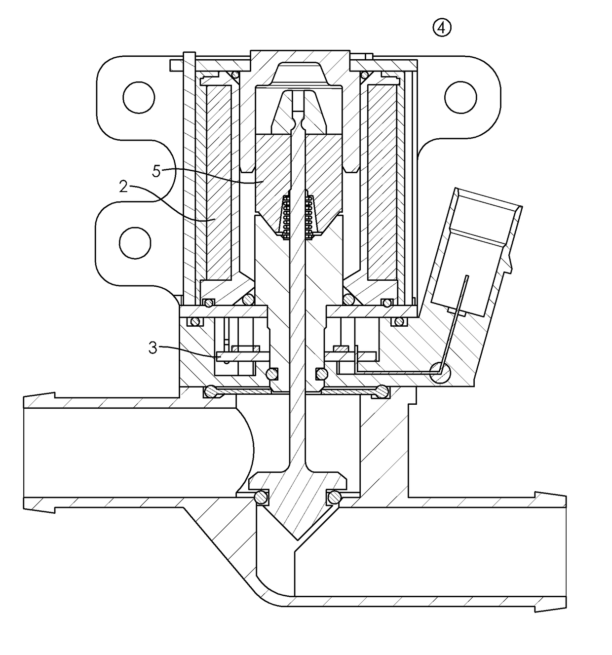
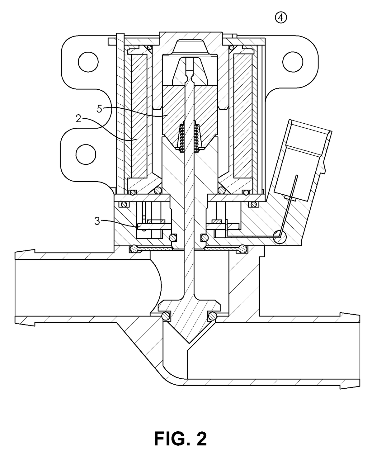
[0032]The actuator 4 shown in FIG. 2 has an anchor 5 actuated by the coil 2 and, on a circuit board, the temperature compensation circuit 3.

[0033]FIG. 2 denotes a coil, and a “bracket”, by means of which the actuator can be attached, for example. Only FIG. 2 denotes a cover, and the valve body, which is substantially Z-shaped in the case shown, wherein in the case shown the central, a short leg is substantially perpendicular to two other legs, which correspond to an inlet and an outlet. Furthermore, in the example shown, a valve tappet 5 is provided in the central leg of the “Z” in order to open or close the fluid passage. In the example shown, the valve tappet also moves substantially perpendicularly to the inlet and the outlet, and a plane o...


PUM

PropertyMeasurementUnit
angleaaaaaaaaaa
angleaaaaaaaaaa
electrical coil resistanceaaaaaaaaaa

Abstract

A temperature compensation circuit including a magnetic coil, wherein an electrical resistance of the magnetic coil increases with increasing temperature. The temperature compensation circuit is electrically connected to the magnetic coil and includes at least has one component whose electrical resistance decreases with increasing temperature. A plurality of components having electrical resistances decreasing with increasing temperature, increases with increasing temperature, and / or substantially constant with increasing temperature may also be provided.

Description

CROSS-REFERENCE TO RELATED PATENT APPLICATION[0001]This application claims priority to German Patent Application No. 10 2016 203486.3 filed on Mar. 3, 2016, the disclosure of which is incorporated herein by reference in its entirety.TECHNICAL FIELD[0002]The invention relates to a magnetic coil, for example for use in an actuator.BACKGROUND[0003]Actuators or control units are used in numerous technical fields, for example to position components or actuate valves. This relates in particular to valves in the field of vehicle technology, which can be subject to extensive temperature fluctuations which also affect the actuators.[0004]The actuators described herein include an anchor which is movable by a magnetic coil, the electrical resistance of which typically increases with temperature. As a result, the actuating force which can act on the anchor becomes lower at higher temperatures since the actuating force is dependent on the coil current. As mentioned above, since the electrical re...

Claims


Application Information

Patent Timeline
Patent Type & Authority Applications(United States)
IPC IPC(8): H01F7/18
CPCH01F7/18H01F7/064H01F27/008F16K13/06H01F7/1607
Inventor MENGES, HOLGER
Owner HANON SYST
Why Eureka
Try Eureka