
Rotor-stator assembly for a gas turbine engine

a gas turbine engine and assembly technology, applied in the direction of stators, machines/engines, mechanical equipment, etc., can solve the problems of poor durability, contact between the blade tips and the facing material, and poor durability, and achieve the effect of being cheap to mak

Active Publication Date: 2019-06-25
SAFRAN HELICOPTER ENGINES
View PDF14 Cites 0 Cited by
  • Summary
  • Abstract
  • Description
  • Claims
  • Application Information

AI Technical Summary

Benefits of technology

[0010]An object of the present invention is thus to provide a pair of coatings that presents uniform and high-performance behavior for all of the above-mentioned main properties, in particular at high temperature, while also being inexpensive to make.
[0014]Such an abrasive / abradable coating pair presents numerous advantages. In particular, the Applicant has found that the abrasive coating made of zirconia-based ceramic material possesses particularly high-performance abrasive behavior when it is associated with an abradable coating made of ceramic-based zirconia material having a void ratio lying in the range 20% to 50% with pores of a size less than or equal to 50 μm. Likewise, the Applicant has also found that the abradable coating made of zirconia-based ceramic material in accordance with the invention possesses satisfactory abradable behavior when it is associated with an abrasive coating made of zirconia-based ceramic material.
[0015]Furthermore, the abradable coating reveals behavior that is uniform over all contact conditions (namely tangential speed, incursion speed, and temperature) and can be used at high temperature (higher than 1100° C.). It is also a material that performs both the function of a thermal barrier and the function of an abradable coating, and its surface state after machining is satisfactory.
[0016]Furthermore, this abrasive / abradable coating pair is easy to make and to repair and it is inexpensive to fabricate. The material based mainly on zirconia can be deposited by thermal spraying, by a sol-gel method, or by sintering for the abradable coating, and these deposition methods are easy to perform.
[0019]Furthermore, the abradable coating layer is made up of at least two layer portions having different void ratios. Having porosity that varies with depth in the abradable coating enhances the resistance of the coating to thermal shocks, enhances its resistance to thermal cycling, and increases the insulating power of the coating (it provides a more effective thermal barrier). The abradable coating layer may also include vertical cracks.
[0020]Also preferably, the abradable coating layer presents a modulus of elasticity lying in the range 4 gigapascals (GPa) to 10 GPa, and a hardness lying in the range 70 on the Rockwell hardness C scale (HRC) to 95 HRC. Such properties give the abradable coating better resistance to thermal shocks and sufficient erosion resistance while also conserving good abradable character.

Problems solved by technology

The search for no clearance or minimum clearance means that it is inevitable that contacts will occur between the tips of the blades and the facing material.
Because of the hardness that is usual for this material, such contacts can be damaging to the tips of the blades.
Nevertheless, they present poor durability when they are used at high temperature (these coatings are subject to oxidation and to diffusion into the matrix of the coatings), and they also present thermomechanical behavior that is limited and not compatible with the looked-for lifetimes. Furthermore, it is relatively expensive to deposit such coatings.
In contrast, its abradability properties are relatively poor and its use is temperature limited.
Nevertheless, such a porous coating presents surface state problems after machining because of the difficulty of shaping and controlling the sizes of the pores and of the grains in the layer.
Unfortunately, such a surface state in the stream of air is harmful to the performance of the engine.
In general, although the abradable / abrasive coating pairs known in the prior art, all demonstrate a particular good property among the main looked-for properties (namely: behavior of the system on contacting, ability to withstand erosion, ability to withstand thermal cycling, and good surface state), none of them makes it possible on its own to optimize all of the looked-for properties.

Method used


Image

  • Rotor-stator assembly for a gas turbine engine
  • Rotor-stator assembly for a gas turbine engine
  • Rotor-stator assembly for a gas turbine engine

Examples


first embodiment

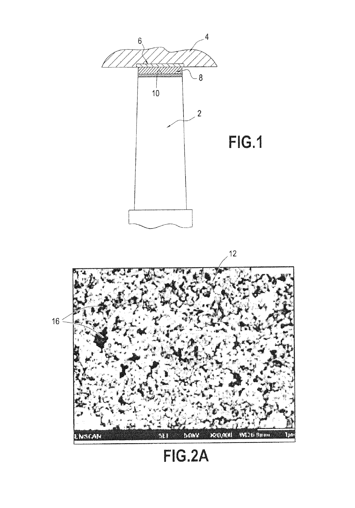
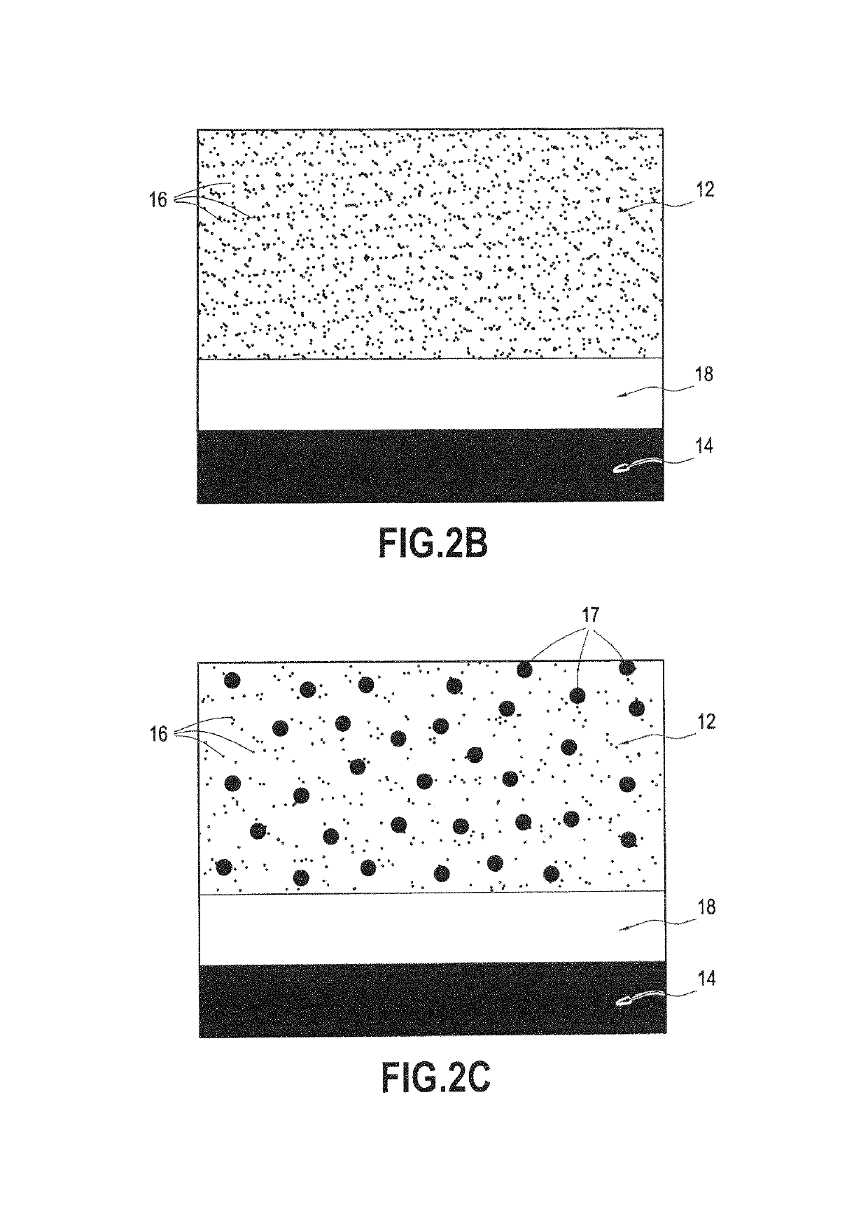
[0040]FIGS. 2A and 2B show a first embodiment respectively in the form of a photograph (scale: 1 μm) and in the form of a diagram, for such a layer 12 constituted mainly by zirconia and deposited on a substrate 14. In this embodiment, the porosity (where pores are represented by black dots 16) is said to be fine, i.e. it is constituted by pores of size less than or equal to 5 μm, and uniform in its distribution across the thickness of the layer. In this example, the distribution of the porosity in the layer is monomodal.

[0041]It should be observed that this layer 12 may be deposited on the substrate via a bonding underlayer 18, e.g. formed by depositing an alloy of the MCrAlY type (where M is Ni, Co, or NiCo), or depositing a platinum aluminide coating, etc.

[0042]Furthermore, in a variant of this first embodiment shown in FIG. 2C, the layer 12 of zirconia also comprises particles 17 of solid lubricant, such as for example particles of hexagonal boron nitride. Such particles make it ...

second embodiment

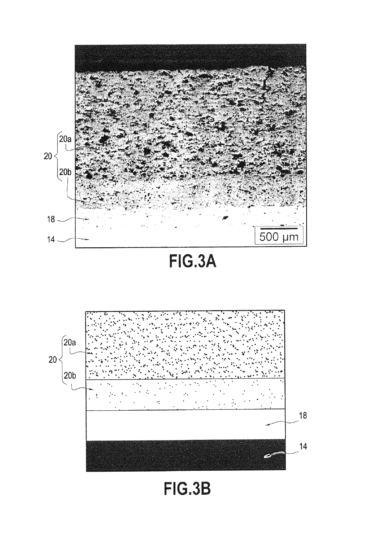
[0043]FIGS. 3A to 3C show a layer 20 deposited on a substrate 14 and suitable for use in constituting the abradable coating of the rotor-stator assembly.

[0044]In this second embodiment, the layer 20 is constituted by two layers 20a and 20b of zirconia having different microstructures. Thus, the layer 20a deposited beside the abrasion zone presents porosity that is high (i.e. having a void ratio lying in the range 20% to 50%), while the layer 20b deposited beside the substrate 14 presents lower porosity (of the order of 10% to 20%).

[0045]A layer is thus obtained that presents high porosity at the surface in order to act as an abradable coating and a denser underlayer beside the substrate in order to act as a thermal barrier. Such variation in porosity across the depth of the abradable coating serves to improve the resistance of the coating to thermal shocks, to improve its resistance to thermal cycles, and to increase the insulating power of the coating (it provides a thermal barrier...

third embodiment

[0049]FIGS. 4A-4B show a layer 24 deposited on a substrate 14 and suitable for use in constituting the abradable coating of the rotor-stator assembly.

[0050]In this third embodiment, the layer 24 is formed by a layer of zirconia with high porosity (i.e. having a void ratio lying in the range 20% to 50%).

[0051]Compared with the first embodiment, the distribution of porosity in the layer in this example is bimodal, i.e. the pores are shared between “fine” pores (i.e. having size less than or equal to 5 μm), and “medium” pores (i.e. having a size lying in the range 15 μm to 50 μm).

[0052]In the photograph of FIG. 4A, the pores of fine size are thus represented by black zones 26, while the pores of medium size are represented by black zones 28. It should be observed that regardless of pore size, the way the pores are distributed in the layer 24 is uniform.

[0053]Other characteristics common to the various embodiments of the layer forming the abradable coating of the rotor-stator assembly a...


PUM

PropertyMeasurementUnit
sizeaaaaaaaaaa
porosityaaaaaaaaaa
sizeaaaaaaaaaa

Abstract

A rotor-stator assembly for a gas turbine engine, the assembly including a rotor having a layer of ceramic material forming an abrasive coating deposited on its tip, the layer being constituted mainly by zirconia and possessing a void ratio less than or equal to 15%, and a stator arranged around the rotor and provided facing the tip of the rotor with a layer of ceramic material forming an abradable coating, the layer being constituted mainly by zirconia possessing a void ratio lying in the range 20% to 50% with pores having size less than or equal to 50 μm.

Description

BACKGROUND OF THE INVENTION[0001]The present invention relates to the general field of rotor-stator assemblies for a gas turbine engine. The invention relates more precisely to optimizing the microstructures of the abrasive coating and of the abradable coating that are deposited respectively on the tip of a rotor and on the inside surface of a stator surrounding the rotor.[0002]A particular field in which the invention is applicable is that of compressors for aeroengine turbines (in particular for airplane engines or helicopter engines).[0003]An aeroengine compressor comprises a compressor casing made up of one or more annular structures situated facing one or more sets of blades that move with relative rotation between the blades and the annular structures. Likewise, an aeroengine turbine comprises a turbine ring made up of an annular structure constituting a single piece or a plurality of touching ring sectors that surround a set of rotary blades driven by combustion gas.[0004]In ...

Claims


Application Information

Patent Timeline
Patent Type & Authority Patents(United States)
IPC IPC(8): F01D5/28C23C4/10C23C4/11F01D25/00F01D25/08F01D9/02F01D11/12C04B35/486C04B35/488
CPCF01D5/284C04B35/488C23C4/11F01D5/288F01D9/02F01D11/125F01D25/005F01D25/08C04B35/486Y02T50/6765C04B2235/3224C04B2235/3225C04B2235/386C04B2235/767F05C2203/0895F05D2240/12F05D2240/15F05D2240/307F05D2300/2285F05D2300/502F05D2300/516F05D2300/611F01D5/20F01D11/122Y02T50/60
Inventor GURT SANTANACH, JULIENCRABOS, FABRICE
Owner SAFRAN HELICOPTER ENGINES
Learn More