Universal mounting ring

a universal mounting and ring technology, applied in the field of universal adapters, can solve the problems of reducing the range of the reader, causing the reader to be easily damaged, and providing an unacceptable finished look

Active Publication Date: 2017-09-07
ASSA ABLOY AB
View PDF4 Cites 23 Cited by
  • Summary
  • Abstract
  • Description
  • Claims
  • Application Information

AI Technical Summary

Benefits of technology

[0007]In accordance with the preferred embodiment of the present invention, a universal mounting ring is provided for securing an electronic device, for example, a radio frequency identification (RFID) reader, within an electrical enclosure. It should be appreciated that the universal mounting ring may also secure other types of readers, including contact and contactless readers, and other types of electronic devices, such as a miniature controller or door interface module. One example of such an enclosure is a conventional electrical junction box. The universal mounting ring provides multiple mounting positions for the electronic device relative to a cover assembly which is utilized to provide an aesthetic cover for the content of the enclosure.

Problems solved by technology

In a typical case where the reader is mounted in a fixed location on a support structure, the range of the reader is susceptible to the materials of the mounting location and other objects within the operating environment.
For example, if the mounting location of a reader is in an operating environment which includes nearby metal, the metal can de-tune the resonant circuit of the reader from the predetermined frequency and drastically reduce the range of the reader.
While this approach is desirable from a functional standpoint, it is often undesirable from an aesthetic standpoint as the housing provides an unacceptable finished look.
For example, the reader housing protrudes from the surface of a wall an unacceptable distance and / or utilizes a cover plate designed solely for the reader but which may not aesthetically match the cover plates used throughout the building and particularly nearby space.
Additionally, because the reader is potted in the plastic housing, the housing cannot be changed.

Method used


Image

  • Universal mounting ring
  • Universal mounting ring
  • Universal mounting ring

Examples


Embodiment Construction

[0040]For simplicity in understanding, the present disclosure is described and illustrated with respect to use with an RFID reader. It should be appreciated that the universal mounting ring may be used with all types of access control readers, including both contactless and contact readers, as well as other types of electronic devices, including miniature controllers and door interface modules.

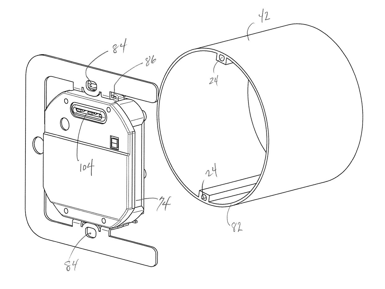
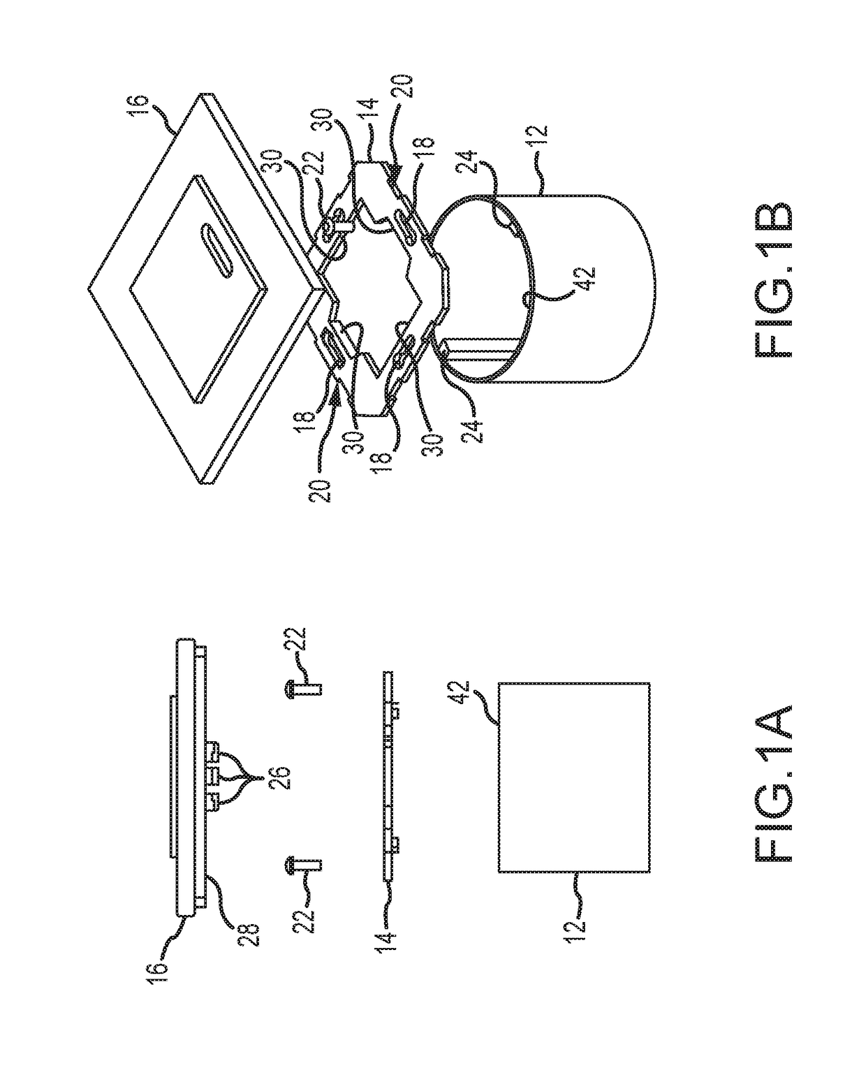
[0041]One embodiment of a prior art electrical junction box 12, mounting bracket 14 and cover assembly 16 is shown in FIGS. 1A and 1B. The junction box 12 is designed to hold an electronic component, such as a light switch. The cover assembly 16 provides an aesthetic closure and finish that covers the contents of the junction box 12. The mounting bracket 14 is attached to the junction box 12 and, in turn, the cover assembly 16 is affixed to the mounting bracket 14. More specifically, a slot 18 is formed in each side or leg 20 of the mounting bracket 14 through which screws 22 extend and thread...


PUM


Abstract

A universal mounting ring has an arcuate or curved upper portion and a plurality of downwardly depending tabs. The universal mounting ring is configured to interface with an electrical enclosure, such as conventional electrical junction boxes to permit a radio frequency identification (RFID) reader to be secured within the enclosure and mate with a wide variety of enclosure cover assemblies manufactured by third parties. The downwardly depending mounting tabs are provided with multiple mounting positions such that the reader may be securely mounted at a plurality of positions relative to a cover assembly.

Description

RELATED APPLICATIONS[0001]This application is a continuation-in-part of co-pending U.S. patent application Ser. No. 29 / 557,095 entitled “Reader Module” having a filing date of Mar. 4, 2016 and U.S. patent application Ser. No. 29 / 557,099 entitled “Reader Module Bracket” having a filing date of Mar. 4, 2016, the entirety of each of which is incorporated herein by reference.FIELD OF THE INVENTION[0002]The present application relates to a universal adapter to permit mounting of an electronic device, such as a contact or contactless reader, miniature controller, door interface module or other electronic device in an electrical enclosure, such as a conventional electrical junction box. The adapter further allows variable positioning of the electronic device or reader within the enclosure and accommodates a wide variety of cover plates to enhance aesthetic finishes.BACKGROUND OF THE INVENTION[0003]Contactless radio frequency identification (RFID) systems typically include at least one read...

Claims


Application Information

Patent Timeline
Patent Type & Authority Applications(United States)
IPC IPC(8): H02G3/08G06K7/10H02G3/14
CPCH02G3/083G06K7/10336H02G3/14G06K7/10009H02G3/123
Inventor PADILLA, TOBY MARKBOUSFIELD, RANDALL DENNIS
Owner ASSA ABLOY AB
Why Eureka
Try Eureka