Stackable cases

a stackable and case technology, applied in the field of stackable cases, can solve the problem of limited application of stackable cases, and achieve the effect of expanding the applicability and/or utility of such a stackable cas

Active Publication Date: 2017-09-14
MAKITA CORP
View PDF14 Cites 62 Cited by
  • Summary
  • Abstract
  • Description
  • Claims
  • Application Information

AI Technical Summary

Benefits of technology

[0006]According to such an embodiment, object(s) such as, for example, beverages, food, etc. can be stored and maintained in a cool state or in a warm state and conveniently carried together, e.g., with a case holding an electric power tool. In this aspect of the present teachings, the convenience of this type of cases can be improved and also types of the objects that can be stored may be extended (expanded).
[0036]According to such an embodiment, the engagement of the latch(es) couples the stackable case to the stackable device in the stacked manner. When the engagement of the latch(es) is released, the stackable case can be separated from the stackable device. Thus, the stackable case and the stackable device may be coupled or separated by engaging or releasing the latch(es), respectively. In this regard, the handling properties of the stackable case and the stackable device can be improved.

Problems solved by technology

Such a known stackable, linkable case is limited to storing only electric power tools and / or accessories thereof.

Method used


Image

  • Stackable cases
  • Stackable cases
  • Stackable cases

Examples


first embodiment

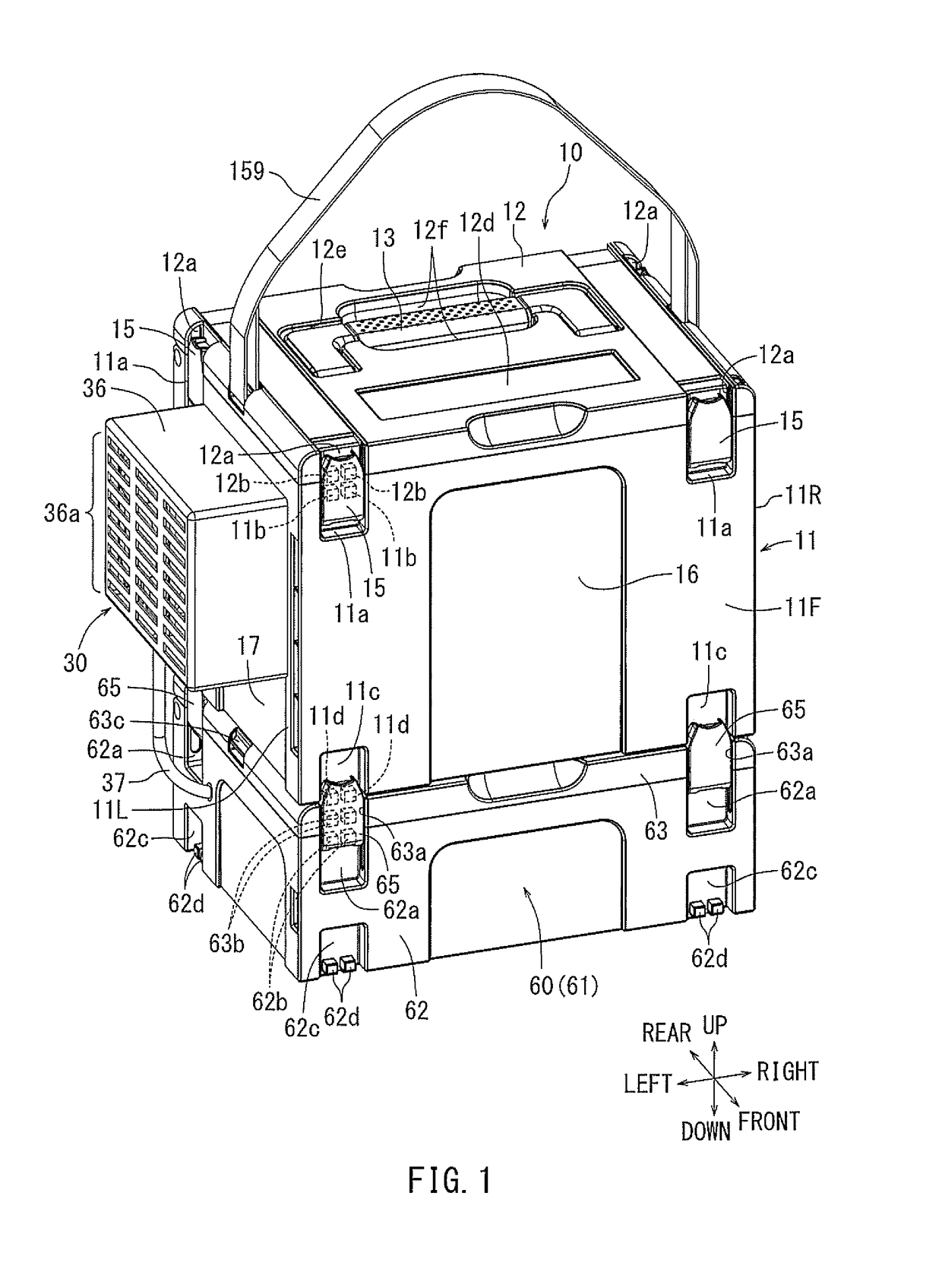
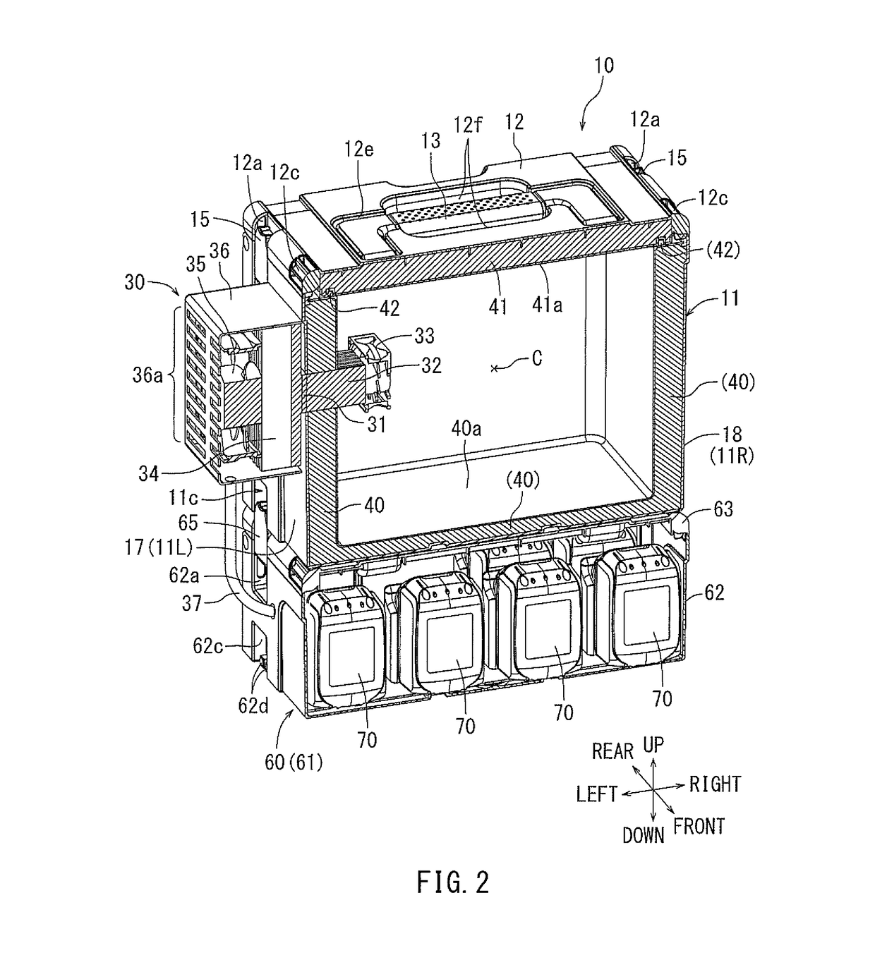
[0083]As will be further described below, in one aspect of the present teachings, a cooling device is preferably provided in or on one of a plurality of stackable cases, which each have the latches 15 and the connection protrusions 11d. FIGS. 1 to 3 show a first representative cooling device 30 which may be mounted in (on) the stepped portion (recess) 17 on the left side surface 11L of the case main body 11. It should be understood that, although the term “cooling device” is used with respect to device 30, this “cooling device” optionally may be configured to also, or instead of cooling, perform a warming / heating function. Thus, the “cooling device” may also be a “cooling / warming device” or simply a “warming device” according to some embodiments of the present teachings. Preferably, thermoelectric devices may be utilized with the present teachings and they operate by applying a voltage (current) across the thermoelectric device, e.g., a solid-state device. However, the present teac...

second embodiment

[0105]The cooling device 51 may be disposed in a second (functional) compartment K, which is partitioned by the partitioning portion 52b of the heat insulation material 52 from the storage compartment C within the case main body 11. The cooling device 51 may include a Peltier element 55, a (cooling-side) heat sink 56, a fan 57, fins 58 and a fan 59. A plurality of exhaust ports (holes) 59a may be formed in the left side of the second compartment K (i.e. in the left side of the case main body 11).

[0106]The heat sink 56 and the fan 57 may be held (supported) by the partition 52b of the heat insulation material 52. An air outlet port (hole) 57a may be provided in the right side of the partition portion 52b in front of the fan 57. The fan 57 is preferably designed to blow the cold air (or hot air, if the current is switched) generated by the Peltier element 55 through this air outlet port 57a into the storage compartment C.

[0107]According to the stackable case 50 of the second embodime...

fifth embodiment

[0119]A stepped portion (protrusion, bulge) 12h may be formed on the inner panel 92a so as to cover or extend across substantially the entire inner surface of the lid 12 and to face the storage compartment C. The heat insulation material 92 (e.g., polystyrene foam, etc.) may be also arranged between the stepped portion 12h (inner panel 92a) and the outer panel 12n of the lid 12 without a gap. The stepped portion (protrusion, bulge) 12h is designed to be fitted into the upper opening of the storage compartment C such that the entire area of the opening of the storage compartment C is closed (covered, sealed) when the lid 12 is closed as shown in FIG. 20. Consequently, the sealing properties of the lid 12 may be further improved as compared to the stackable case 95 of the fifth embodiment, which does not include a bulged portion of the lid 12 that protrudes into the opening of the storage compartment C. As shown in FIG. 19, a logo display area 12i may be arranged in the middle of the ...


PUM


Abstract

A stackable case includes a cooling and / or heating device, such as a Peltier element, so that the stackable case can be used as a cooler and / or warmer for storing beverages, food, etc. A power source device, in which a plurality of battery packs is housed, supplies power to the Peltier element and one or more fans. The power supply device has latches for detachably joining or linking it to the stackable case in a stacked manner.

Description

CROSS-REFERENCE[0001]This application claims priority to Japanese patent application serial number 2016-46025, filed on Mar. 9, 2016, and to Japanese patent application serial number 2016-154532, filed on Aug. 5, 2016, the contents of which are incorporated herein by reference in their entirety.TECHNICAL FIELD[0002]The present invention generally relates to stackable cases that enable a plurality of cases to be linked or coupled together and carried together in an stacked manner. In a non-limiting example, one of the cases may be, e.g., a cooler / warmer, one of the cases may be designed, e.g., to house / hold an electric power tool, such as a driver drill, impact wrench, portable saw, etc., and one of the cases may be designed, e.g., to hold a power supply device containing and / or utilizing one or more power tool battery packs.BACKGROUND ART[0003]Japanese Laid-Open Patent Publication No. 2013-226621 discloses a design for a stackable case that is configured to link or couple an upper c...

Claims


Application Information

Patent Timeline
Patent Type & Authority Applications(United States)
IPC IPC(8): B65D21/02B25H3/00B65D81/38H02J7/00B65D25/04F25B21/04F25D17/06F25D23/02A45F3/14B65D45/16
CPCB65D21/0217A45F3/14B25H3/006B65D81/3813B65D45/16B65D25/04F25B2321/0212F25D17/06F25D23/028H02J7/0013A45F2003/142F25B2321/023F25B21/04B25H3/02B65D21/0228B65D81/18B65D81/3484H02J2310/22H02J7/0045F25D11/00H02J7/0044F25D2400/12A45C7/0045A45C11/20A45C13/02
Inventor HORI, SHIROHORI, ATSUSHI
Owner MAKITA CORP
Why Eureka
Try Eureka