Substrate holding device

a technology for holding devices and substrates, applied in vacuum evaporation coatings, chemical vapor deposition coatings, coatings, etc., can solve the problem of substrate heat up to a slightly greater extent, and achieve the effect of improving the temperature homogeneity of the surface temperature of the substra

Active Publication Date: 2017-09-14
AIXTRON AG
View PDF4 Cites 6 Cited by
  • Summary
  • Abstract
  • Description
  • Claims
  • Application Information

AI Technical Summary

Benefits of technology

[0006]The object of the invention is to take measures with which the temperature homogeneity of the surface temperature of the substrate can be improved.

Problems solved by technology

One disadvantage is that the substrate heats up to a slightly greater extent in the area of its contact points on the carrying protrusions than in the remaining area.

Method used


Image

  • Substrate holding device
  • Substrate holding device
  • Substrate holding device

Examples


Embodiment Construction

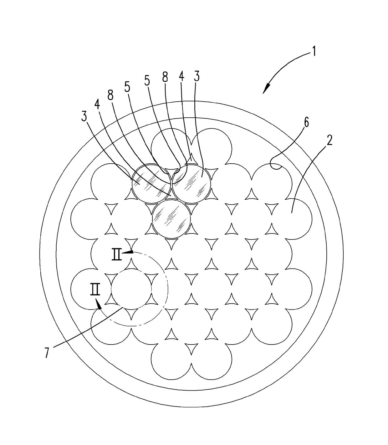
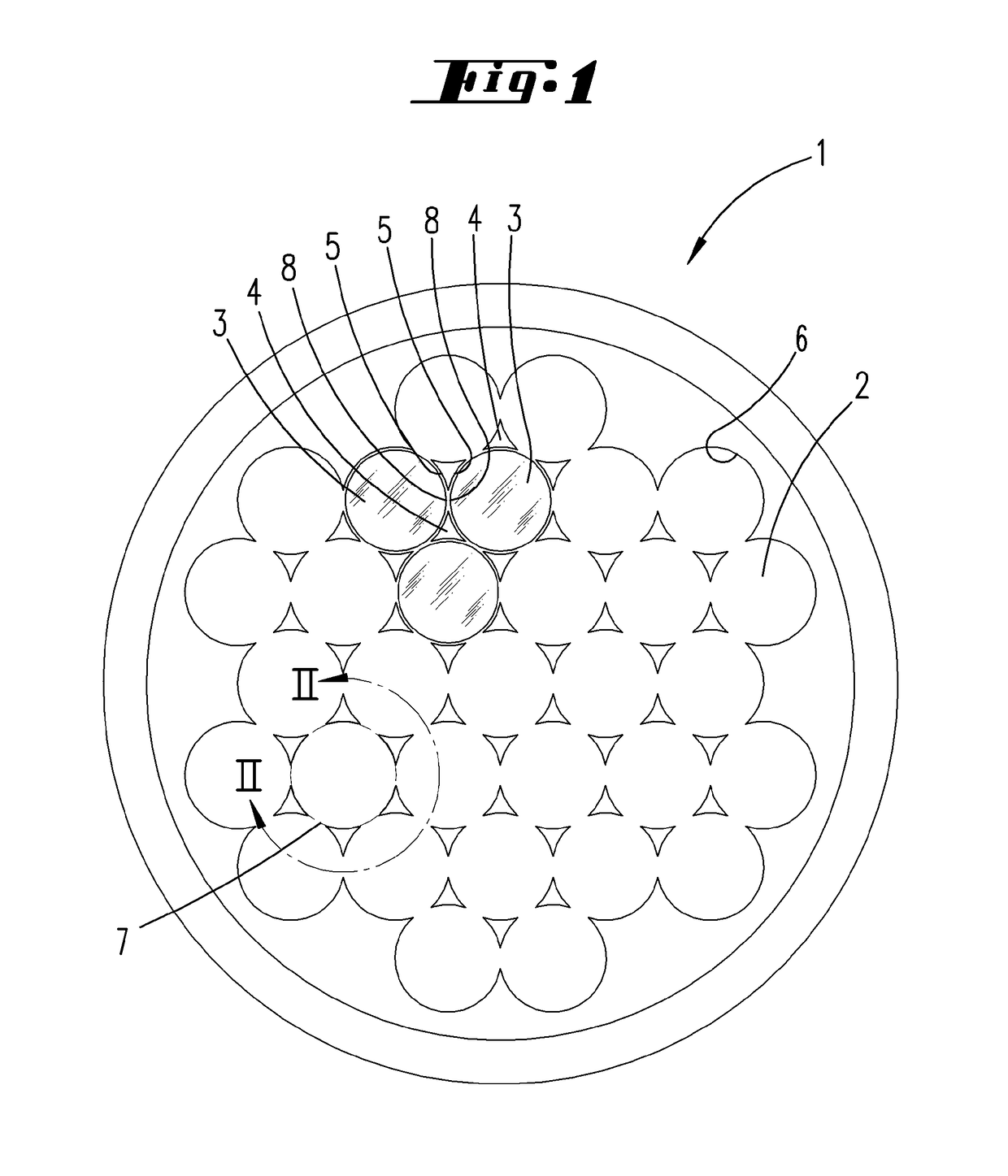
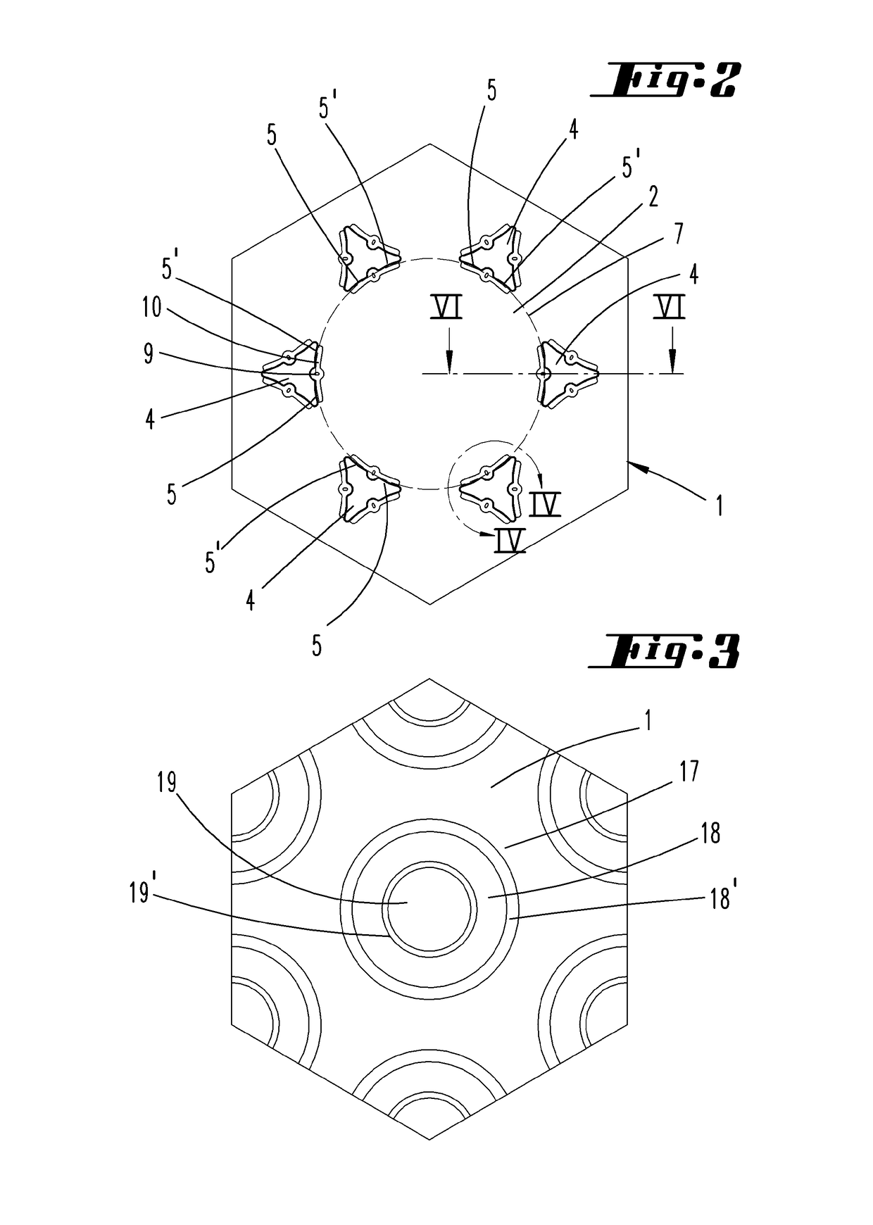
[0025]The substrate holder 1 depicted on the drawings is used as a susceptor in a CVD reactor. A CVD reactor has a housing that is outwardly sealed gastight, as schematically illustrated in DE 10 2011 055 061 A1. Located inside of the housing at a lower height level is a heater, which can be a resistance heater. This heater is used to bring the susceptor 1 arranged above the heater to a surface temperature. Located on the upper side of the susceptor 1 is a plurality of bearing areas 2, each for mounting a circular disk-shaped substrate. Each bearing area 2 is bordered by a total of six roughly triangular sockets 4. Each socket can form three individual positioning flanks 5 or three pairs of positioning flanks 5, 4′. This yields a hexagonal arrangement of circular bearing areas 2, each for accommodating a substrate 3, the edge 8 of which runs along the outline contour line 7 of the respective bearing area 2. As a consequence, a total of six individual positioning flanks 5 or six pair...


PUM

PropertyMeasurementUnit
diameteraaaaaaaaaa
diameteraaaaaaaaaa
areaaaaaaaaaaa

Abstract

A device for holding at least one substrate in a process chamber of a CVD or PVD reactor includes a flat upper side on which at least one bearing area for the at least one substrate is located. An outline contour line corresponding to the outline contour of the substrate is flanked by positioning edges for positioning a respective section of an edge of the substrate. The device further includes carrying protrusions projecting from a bearing area base surface of the bearing area that is surrounded by the outline contour line. The carrying protrusions have contact surfaces that are raised in relation to the bearing area base surface, on which contact surfaces the substrate can be placed. In order to improve the temperature homogeneity of the surface of the substrate, each of the carrying protrusions originate from a recess of the bearing area base surface.

Description

FIELD OF TECHNOLOGY[0001]The invention relates to a device for holding at least one substrate for use in a process chamber of a CVD or PVD reactor, with a flat upper side on which at least one bearing area for the at least one substrate is located, wherein an outline contour line corresponding to the outline contour of the substrate is flanked by positioning flanks for the positionally fixed contacting of a respective section of an edge of the substrate, and with carrying protrusions projecting from a bearing area base surface of the bearing area that is surrounded by the outline contour line, which have contact surfaces that are raised in relation to the bearing area base surface, on which the substrate can be placed.PRIOR ART[0002]A device of this kind is previously known from U.S. Pat. No. 5,645,646. The publication discloses a susceptor with a bearing area for receiving a substrate, wherein the bearing area is bordered by a positioning flank, which envelops an outline contour li...

Claims


Application Information

Patent Timeline
Patent Type & Authority Applications(United States)
IPC IPC(8): C23C14/50C23C16/458
CPCC23C16/4583C23C14/50H01L21/68735H01L21/6875
Inventor SUFAN, EDUARDO OSMAN PINIEROCLAESSENS, DANIELBOYD, ADAM
Owner AIXTRON AG
Why Eureka
Try Eureka