Float-swing hydraulic support
a hydraulic support and float technology, applied in the direction of mine roof supports, earth-moving drilling, mining structures, etc., can solve the problems of high labor intensity, low production efficiency, long cycle, etc., and achieve the effect of improving production efficiency, reducing intermediate links, and improving safety and stability
- Summary
- Abstract
- Description
- Claims
- Application Information
AI Technical Summary
Benefits of technology
Problems solved by technology
Method used
Image
Examples
example 1
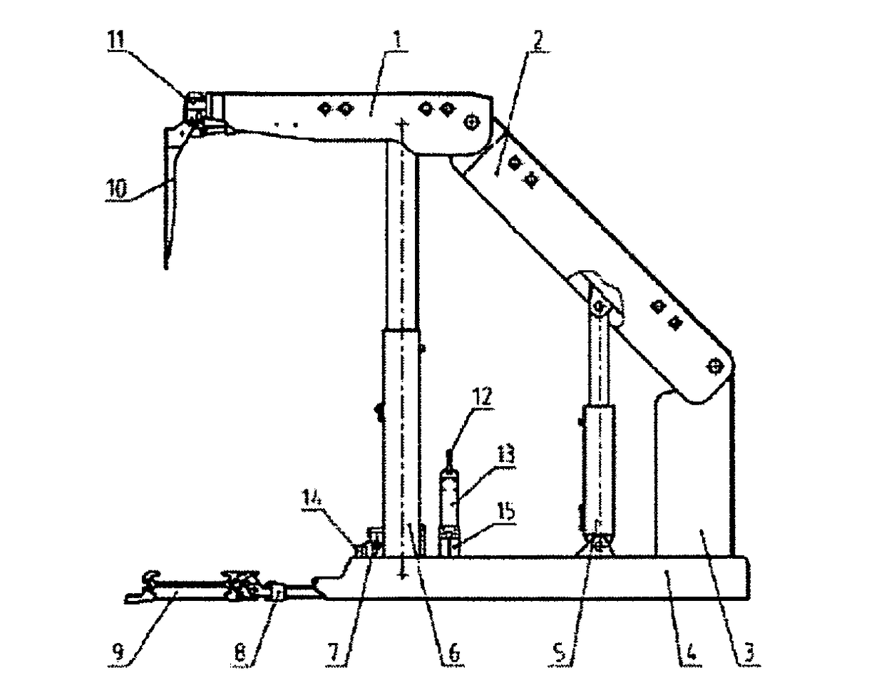
[0020]As shown in FIG. 1, the float-swing hydraulic support provided in the present invention mainly comprises a top beam 1, a shield beam 2, an elevating frame 3, a base 4, an adjusting jack 5, two float hydraulic columns 6, a base raising unit 7, an advancing unit 8, a scraper conveyor 9, a face guard unit 10, a telescopic beam unit 11, a hydraulic control valve block 12, a valve block support 13, a front bridge piece 14, and a rear bridge piece 15. The top beam 1, shield beam 2, elevating frame 3, and base 4 are made of steel plate or profile steel by welding. The front bridge piece 14 and the rear bridge pieces 15 are made of thick steel plates by welding, and are welded with the base 4 as a whole. The hydraulic control valve block 12 is a manually operated valve block or electro-hydraulically remotely-controlled valve block, serves as a manipulation center of the actions of the support, and can be manually operated or electro-hydraulically remotely-controlled. The front end of ...
example 2
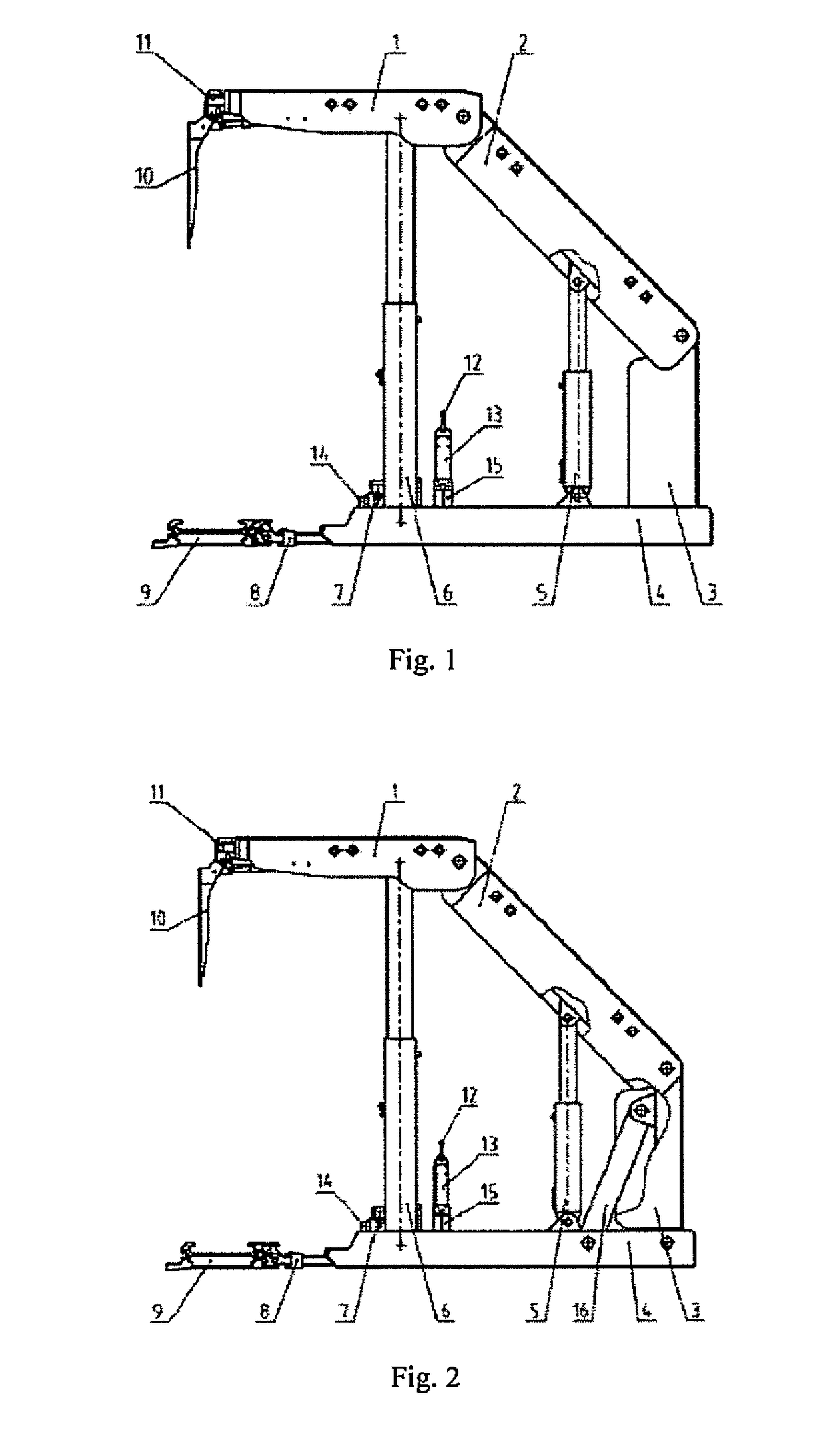
[0023]As shown in FIG. 2, example 2 is essentially the same as the example 1. Herein, the description of identical parts is omitted. The difference lies in: a diagonal bracing 16 comprising one bracing bar used separately or two bracing bars used in parallel is arranged between the upper part of the elevating frame 3 and the base 4.
Working Process:
[0024]To raise the support, the hydraulic control valve block 12 is operated, so that a high-pressure liquid enters into a big chamber of the two float hydraulic columns 6 and the adjusting rack 5, and the top beam 1 and the shield beam 2 swing and move upward; the shield beam 2 stops moving upward when it comes into contact with the roof, while the top beam 1 further swing slightly around the hinge shaft between the top beam 1 and the shield beam 2 under the action of the two float hydraulic columns 6, till the initial support resistance of the support is reached; the telescopic beam unit 11 and the face guard unit 10 extend or unfold acc...
PUM
 Abstract
Description
Claims
Application Information
 - R&D
- Intellectual Property
- Life Sciences
- Materials
- Tech Scout
- Unparalleled Data Quality
- Higher Quality Content
- 60% Fewer Hallucinations
Browse by: Latest US Patents, China's latest patents, Technical Efficacy Thesaurus, Application Domain, Technology Topic, Popular Technical Reports.
© 2025 PatSnap. All rights reserved.Legal|Privacy policy|Modern Slavery Act Transparency Statement|Sitemap|About US| Contact US: help@patsnap.com


