
Light source module and lighting apparatus including the same

a technology of light source module and lighting apparatus, which is applied in the direction of lighting and heating apparatus, instruments, semiconductor devices of light sources, etc., can solve problems such as hot spots, and achieve the effect of slimming a lighting apparatus

Inactive Publication Date: 2017-09-14
SAMSUNG ELECTRONICS CO LTD
View PDF4 Cites 25 Cited by
  • Summary
  • Abstract
  • Description
  • Claims
  • Application Information

AI Technical Summary

Benefits of technology

The invention aims to prevent the occurrence of bright spots in lighting apparatuses while allowing for slimming.

Problems solved by technology

However, in a case in which LED elements are used as surface light sources, due to light characteristics thereof, such as high linearity, hot spots may occur due to non-uniform brightness distribution.

Method used


Image

  • Light source module and lighting apparatus including the same
  • Light source module and lighting apparatus including the same
  • Light source module and lighting apparatus including the same

Examples


Embodiment Construction

[0024]Hereinafter, example embodiments of the present inventive concepts will be described with reference to the accompanying drawings.

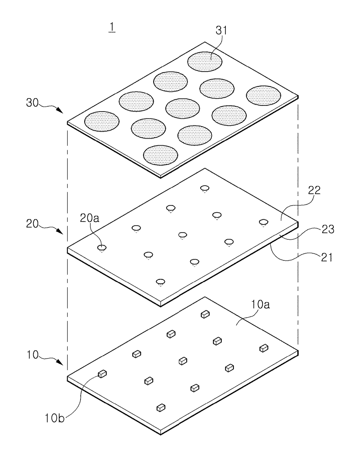
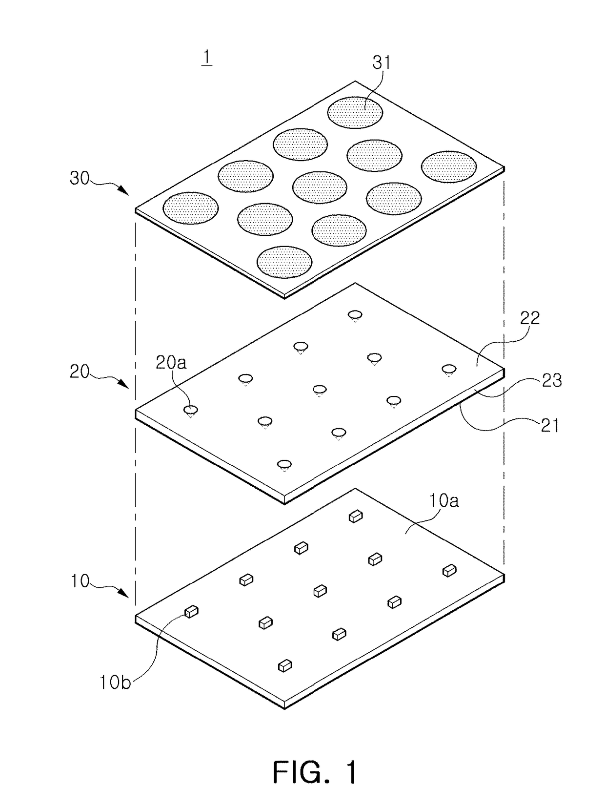
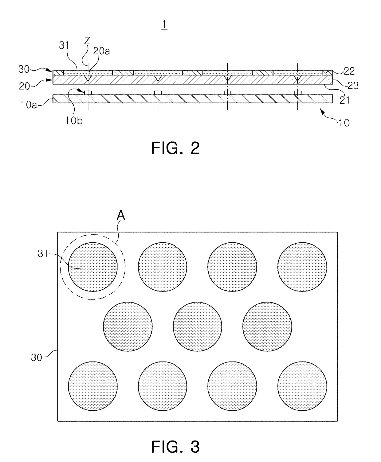
[0025]With reference to FIGS. 1 to 3, a light source module according to some example embodiments will be described. FIG. 1 is an exploded perspective view of a light source module according to some example embodiments, FIG. 2 is a schematic cross-sectional view of the light source module of FIG. 1, and FIG. 3 is a plan view of FIG. 2.

[0026]With reference to FIGS. 1 to 3, a light source module 1 according to some example embodiments may include a light source layer 10, a light guide plate 20 on the light source layer 10, and a filter sheet 30 attached to an upper surface of the light guide plate 20.

[0027]The light source layer 10 may include one or more light sources 10b. A light source 10b may be an optoelectronic device configured to generate light having a desired (and / or alternatively predetermined) wavelength based on driving power applied to th...


PUM


Abstract

A light source module includes a light source, a light guide plate on the light source and including at least one recess portion in an upper surface thereof, and a filter sheet on an upper surface of the light guide plate and having a pattern. The pattern may be configured to partially reflect and partially transmit light emitted from the light source through the light guide plate.

Description

CROSS-REFERENCE TO RELATED APPLICATIONS[0001]This application claims benefit of priority to Korean Patent Application No. 10-2016-0029453 filed on Mar. 11, 2016 in the Korean Intellectual Property Office, the disclosure of which is incorporated herein by reference in its entirety.BACKGROUND[0002]1. Field[0003]The present inventive concepts relate to a light source module and a lighting apparatus including the same.[0004]2. Description of Related Art[0005]Semiconductor light emitting diode (LED) elements have been used as light sources in various types of electronic products such as television sets, mobile phones, personal computers, notebook computers, personal digital assistants (PDAs), and the like, as well as for light sources of lighting apparatuses.[0006]However, in a case in which LED elements are used as surface light sources, due to light characteristics thereof, such as high linearity, hot spots may occur due to non-uniform brightness distribution. In order to limit and / or ...

Claims


Application Information

Patent Timeline
Patent Type & Authority Applications(United States)
IPC IPC(8): F21K9/61F21V15/015H01L33/48F21V9/00F21V3/02H01L33/60F21V29/77F21K9/27F21V9/40
CPCF21K9/61F21V29/77F21V15/015F21K9/27F21Y2103/10F21V3/02H01L33/60H01L33/486F21Y2115/10F21V9/00F21V7/22F21V2200/00F21V3/049F21V29/74F21Y2105/10G02B6/0016G02B6/0021G02B6/0023G02B6/0051G02B6/0055
Inventor MOON, KYUNG MIHA, SANG WOOSONG, JONG SUPARIYOSHI, TETSUOCHO, JUNJI, WON SOO
Owner SAMSUNG ELECTRONICS CO LTD
Learn More