Stroboscope with Integral Optical Reflective Sensor Used as a Flash Trigger

Active Publication Date: 2017-09-14
MONARCH INT
View PDF5 Cites 5 Cited by
  • Summary
  • Abstract
  • Description
  • Claims
  • Application Information

AI Technical Summary

Benefits of technology

The present invention is a stroboscope with an integrated optical sensor. This optical sensor helps trigger the stroboscope when a specific event occurs on a rotating or vibrating target. The stroboscope can synchronize its flash rate with the target's movement, eliminating the need for manual adjustment. The integrated optical sensor allows for one-handed operation and remote operation. The stroboscope also includes a filtering and conditioning circuit to extract a valid trigger from the reflected light source. Overall, the present invention provides a more efficient and effective tool for visual inspection and stopping motion.

Problems solved by technology

Unless the stroboscope has special blanking capability, the stroboscope flash will cause the optical sensor to re-trigger which will cause another flash and so on, leading to unstable operation.
The cabling of the sensor to the stroboscope and its accessories may pose a danger around moving machinery.

Method used


Image

  • Stroboscope with Integral Optical Reflective Sensor Used as a Flash Trigger
  • Stroboscope with Integral Optical Reflective Sensor Used as a Flash Trigger
  • Stroboscope with Integral Optical Reflective Sensor Used as a Flash Trigger

Examples


Embodiment Construction

[0017]All illustrations of the drawings are for the purpose of describing selected versions of the present invention and are not intended to limit the scope of the present invention.

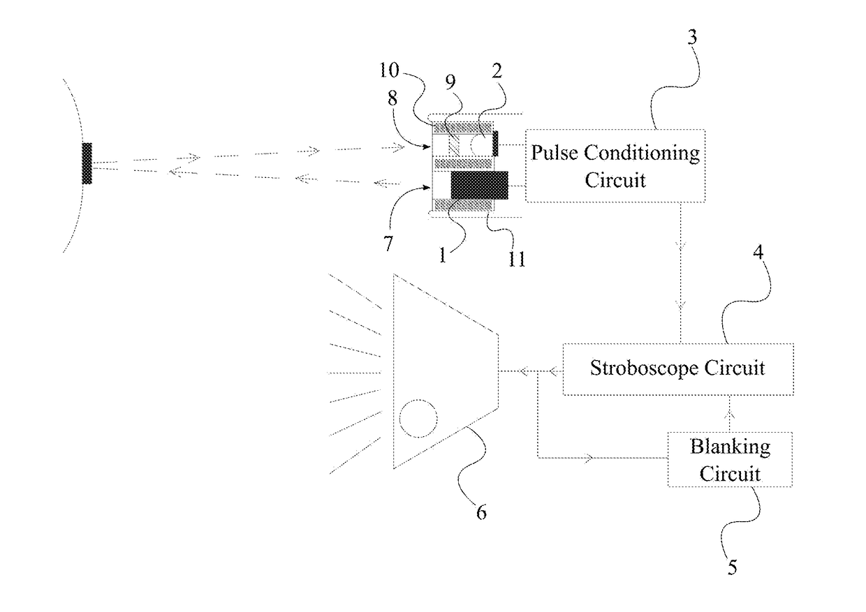
[0018]The present invention is configured to address multiple drawbacks of existing stroboscopes. As an example, the present invention eliminates the need to continuously adjust the flash rate of the stroboscope until the target appears to be still. The present invention provides an apparatus in which an optical sensor is integrated into a stroboscope so that the stroboscope can be used to study periodic motion without the need for manually adjusting the stroboscope. The optical sensor and the stroboscope operate as a single assembly. Therefore, the present invention also enables one-handed operation which is not possible with traditional stroboscopes that function with an external optical sensor. Additionally, the present invention utilizes a filtering and conditioning circuitry to extract a valid trigg...


PUM


Abstract

A stroboscope with an integral optical reflective sensor, which can be removable or fixed, contains a light emitting source, a light sensitive receiver, a pulse conditioning circuit, a stroboscope circuit, a blanking circuit, and a stroboscope light source. The light emitting source projects a light beam to a reflective target. The reflected light beam from the reflective target is detected by the light sensitive receiver. The pulse conditioning circuit generates a set of electrical pulses coincident with the reflected light beam which are sent to the stroboscope circuit. Depending on the signal received by the stroboscope circuit, the stroboscope light source is triggered. The blanking circuit prevents false triggering of the stroboscope light source by introducing a time delay. The time delay is applied when the stroboscope light source is switched on and for a finite time after the stroboscope light source is switch off.

Description

[0001]The current application claims a priority to the U.S. Provisional Patent application Ser. No. 62 / 305,771 filed on Mar. 09, 2016.FIELD OF THE INVENTION[0002]The present invention relates generally to the field of visual inspection to stop motion. More specifically, the present invention is an optical sensor integrated into a stroboscope allowing a user to synchronize the stroboscope flash to specific events on a rotating or vibrating target. The optical sensor is used as a trigger for the flash when the stroboscope is in use. The optical sensor may be fixed to the stroboscope or may be removable to be used remotely.BACKGROUND OF THE INVENTION[0003]Stroboscopes are used in the industry to stop motion and allow inspection of reciprocating or rotating machinery or to determine the rate of reciprocation or speed of rotation. The typical mode of operation is asynchronous whereby the operator manually adjusts the flash rate until the moving target appears to be visually static. Unles...

Claims


Application Information

Patent Timeline
IPC IPC(8): G01J1/44H05B33/08G01J1/02G01J1/08G01J1/06G01J1/04H05B44/00
CPCG01J1/44G01J1/06G01J1/0488G01J1/0219G01J2001/4473H05B33/0854G01J2001/4238G01J2001/446G01J1/08G01P3/40H05B45/12F21S10/06G01S17/50
Inventor WOOLFSON, ALAN J.
Owner MONARCH INT
Why Eureka
Try Eureka