Supercharge Your Innovation With Domain-Expert AI Agents!

Method for manufacturing light guide plate mold

a manufacturing method and technology for light guide plates, applied in the field of display technology, can solve the problems of light guide plates not meeting requirements and severely affecting the product pass rate of light guide plates, and achieve the effects of improving yield and manufacturing efficiency, and high flatness

Active Publication Date: 2017-09-14
WUHAN CHINA STAR OPTOELECTRONICS TECH CO LTD
View PDF15 Cites 7 Cited by
  • Summary
  • Abstract
  • Description
  • Claims
  • Application Information

AI Technical Summary

Benefits of technology

This patent is about a method for making a mold for a light guide plate. The method uses software to create a 3D model of the light guide plate and simulates how it would look if it were produced using the mold. By correcting any deformation in the model, the mold is created to produce a light guide plate that has minimal warping or distortion. This method allows for a higher yield and efficiency in the manufacturing process for light guide plates.

Problems solved by technology

However, during molding of a light guide plate in a mold, due to various factors, such as non-uniform shrinking among various portions of the light guide plate, non-uniform temperature, and inconsistent molecule motion, the light guide plate may get warped and deformed, making the flatness of the light guide not meet requirements and thus severely affecting the product pass rate of the light guide plate.

Method used


Image

  • Method for manufacturing light guide plate mold
  • Method for manufacturing light guide plate mold
  • Method for manufacturing light guide plate mold

Examples


Embodiment Construction

[0023]A clear and complete description will be given to technical solutions of embodiments of the present invention with reference to the attached drawings of the embodiments of the present invention. However, the embodiments so described are only some, but not all, of the embodiments of the present invention. Other embodiments that are available to those having ordinary skills of the art without the expense of creative effort and endeavor are considered belonging to the scope of protection of the present invention.

[0024]Further, the following descriptions of the various embodiments are made with reference to the attached drawings for illustrating, in an exemplary way, specific embodiments to which the present invention is applicable. Directional terminology, such as “up”, “down”, “front”, “rear”, “left”, “right”, “internal”, “external”, and “side”, used in the present invention are described according to the direction shown in the drawings and are not intended to indicate or sugges...


PUM

PropertyMeasurementUnit
size parameteraaaaaaaaaa
sizeaaaaaaaaaa
sizeaaaaaaaaaa

Abstract

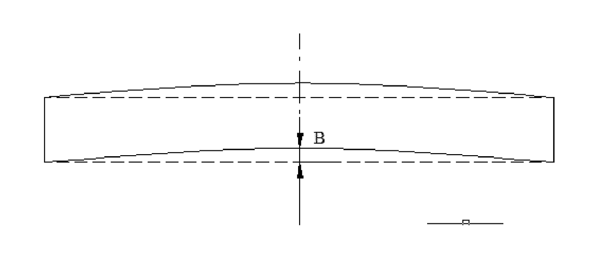
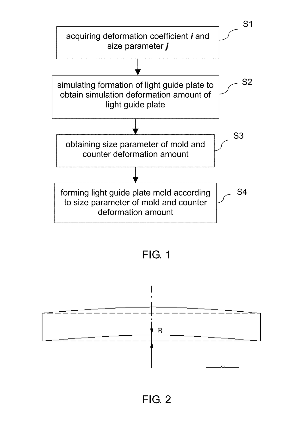
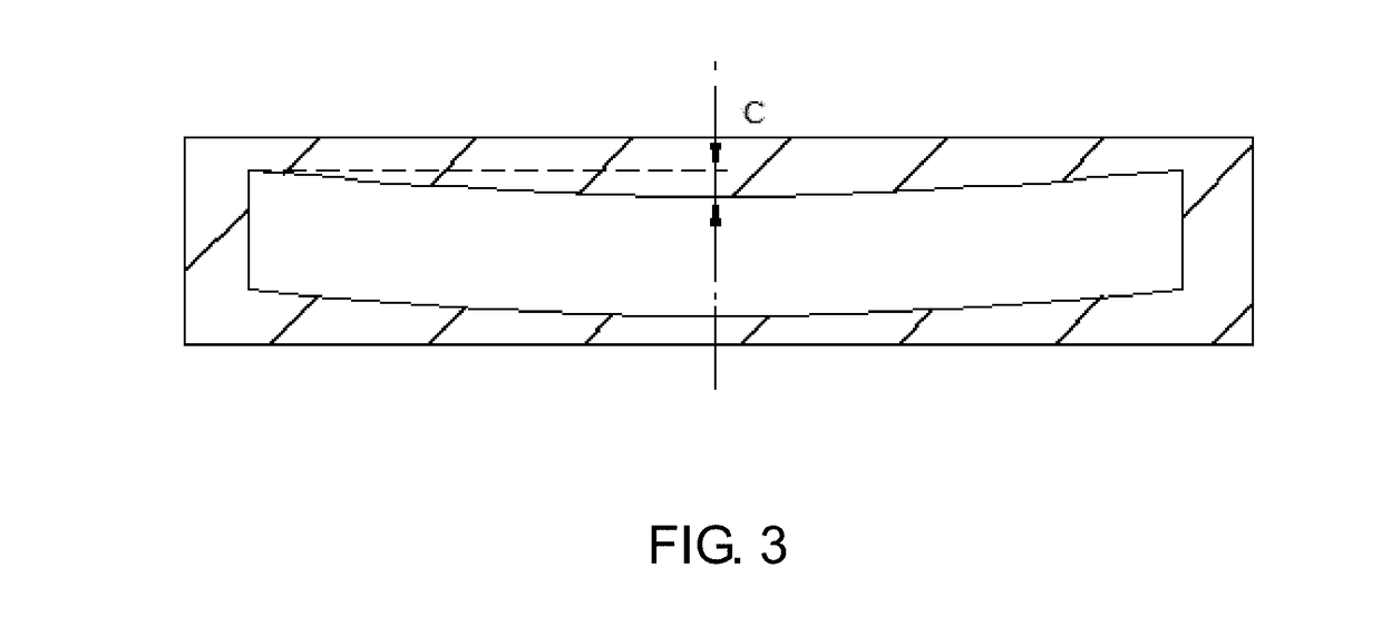
A method for manufacturing a light guide plate mold includes: acquiring a deformation coefficient i, where 1<i≦1.12, and a size parameter j, where 0.03 mm<j≦0.05 mm; applying digital simulation software to simulate a formation process of an original three-dimensional model for a light guide plate so as to acquire a simulation deformation amount of the light guide plate; multiplying the simulation deformation amount with the deformation coefficient i to obtain a counter deformation amount of a light guide plate mold; and subtracting the size parameter j from a length and a width of the light guide plate to obtain length and width dimensions of the light guide plate mold; and forming the light guide plate mold according to the counter deformation amount of the light guide plate mold and length and width dimensions of the light guide plate mold. A light guide plate manufactured with such a mold shows relatively high flatness.

Description

BACKGROUND OF THE INVENTION[0001]1. Field of the Invention[0002]The present invention relates to the field of display technology, and in particular to a method for manufacturing a light guide plate mold.[0003]2. The Related Arts[0004]A backlight module is one of the key components of a panel of a liquid crystal display. Since liquid crystal itself is not luminous, a function of the backlight module is to provide sufficient illuminations and uniformly distributed light source for the liquid crystal display for normally displaying images. In the backlight module, a light guide plate provides essential functionality thereof.[0005]Heretofore, the manufacture of light guide plates is generally achieved through injection molding with molds. However, during molding of a light guide plate in a mold, due to various factors, such as non-uniform shrinking among various portions of the light guide plate, non-uniform temperature, and inconsistent molecule motion, the light guide plate may get wa...

Claims


Application Information

Patent Timeline
Patent Type & Authority Applications(United States)
IPC IPC(8): F21V8/00B29D11/00B29C33/38G02B27/00
CPCG02B6/0065G02B27/0012B29L2031/757B29C33/3835B29C33/3842B29D11/00971B29C45/0025B29D11/00663
Inventor ZHANG, WEI
Owner WUHAN CHINA STAR OPTOELECTRONICS TECH CO LTD
Features
  • R&D
  • Intellectual Property
  • Life Sciences
  • Materials
  • Tech Scout
  • Unparalleled Data Quality
  • Higher Quality Content
  • 60% Fewer Hallucinations
Learn More