Photovoltaic mounting system

a photovoltaic array and mounting system technology, applied in the direction of photovoltaic supports, heat collector mounting/supports, light and heating apparatus, etc., can solve the problems of inconvenient installation, inconvenient maintenance, and inability to meet the needs of users, and achieve the effect of convenient holding

Active Publication Date: 2017-09-14
TESLA INC
View PDF0 Cites 7 Cited by
  • Summary
  • Abstract
  • Description
  • Claims
  • Application Information

AI Technical Summary

Benefits of technology

[0007]During installation, one embodiment of the present assembly can be snapped onto the edge of a first photovoltaic module when the edge of the module is held up in the air by the installer. The assembly can then be lowered onto the roof and function as a temporary kickstand until the assembly is securely attached to the roof. After the assembly is attached, it can provide a convenient platform for a second photovoltaic module to be attached thereto. This process can be repeated such that an array of photovoltaic modules can be quickly laid out on the roof.
[0008]The present system is well suited for use with trapezoidal metal roofs, and may include a pair of self-tapping screws that enables direct attachment to such roofs. Several optional systems are provided for preventing the self-tapping screws from falling out of the mounting assembly during installation. As a result, the installer can manually snap the mounting system onto the first module, lower the module onto the roof, and secure the mounting assembly by driving the self-tapping screws through the metal without the possibility of losing or having to fumble with loose screws.
[0009]In one embodiment, the assembly has a narrow elongated base that can be easily held by the installer with one hand. Such an assembly may function as a lever when rotating the connector portion into a groove formed in a photovoltaic (PV) module frame to lock it onto the side edge of the PV module's frame.
[0010]Preferably, the present assembly permits some module-to-module movement and or alignment during and after installation of the array. This can be accomplished by a module-to-module connector that may optionally slide, pivot and / or rotate slightly with respect to the main body of the assembly. In some embodiments, it may be necessary to pivot the assembly in the opposite direction of attachment to release the connector portion from the groove in the PV module frame to allow it to be slid laterally along the frame to the desired location.
[0011]A further advantage of the present system is that it can used to design an array that does not require module-to-module interlocks (e.g.: interlocks that are not supported from below) in addition to supporting feet that connect one module to another. Traditional grooved frame and standard frame arrays involve two different structures—feet that support the array above the roof (that typically also connect modules together), and interlock connectors that connect adjacent modules together (but are not necessarily supported from below). The use of these two different structures has become a common way to position the feet that support the array at locations that may best correspond to preferred roof connection points. By contrast, the present system uses only one type of connector assembly. Preferably, the present connector is positioned to support each module at four locations around its frame, without the need for secondary module-to-module interlock-style connectors and the without requiring that the assemblies be positioned directly over one of the roof rafters.
[0012]A further advantage of the present system is that it can be mounted to trapezoidal metal roofs, while providing lateral stability. Such systems can make use of assistance clamps that connect to side portions of the trapezoidal roofs. The assistance clamps can take the form of a strap that can be placed into tension over a portion of a narrow elongated base by securing it with mounting screws to either side of the trapezoidal projection. This additional feature may allow such a PV mounting system to be used in coastal areas with high winds.

Problems solved by technology

Unfortunately, these existing systems often are complex, involve many parts, are expensive, and take an undesirably long time to install.
Moreover, the installation of these systems typically requires specialized tools, or a number of different tools.
Trapezoidal roof mounting systems are not secured into building rafters.
This can present several problems.
First, working with small screws requires installers to fumble with small, loose parts while on the roof, as he or she tries to position and fasten them.
Second, due to heat, any rooftop solar system, and in particular one located on a thermally conductive metal roof needs to have sufficient flexibility to account for thermal expansion and contraction through thousands of thermal cycles over the lifetime of a system.
This problem is not addressed by mounting systems that are simply screw-fastened onto metal roofs.
Third, due to the large number of parts used, existing trapezoidal roof mounting systems typically require excessive time to install.
Fourth, existing trapezoidal roof mounting systems typically do not provide for module-to-module grounding; separate grounding wires typically need to be attached to these mounting systems.

Method used


Image

  • Photovoltaic mounting system
  • Photovoltaic mounting system
  • Photovoltaic mounting system

Examples


Embodiment Construction

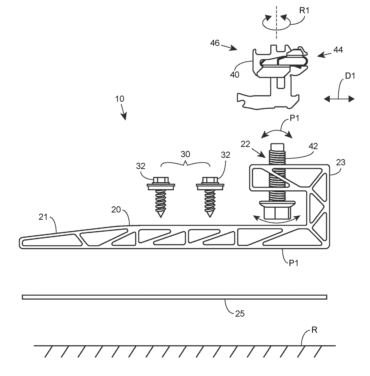
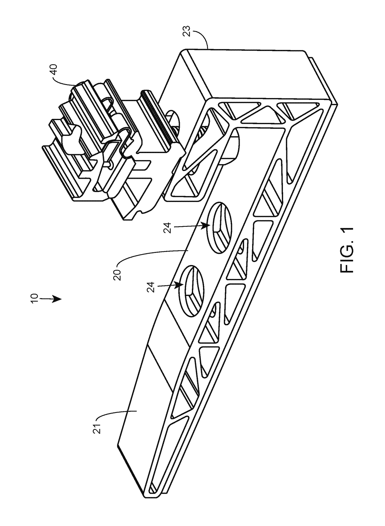
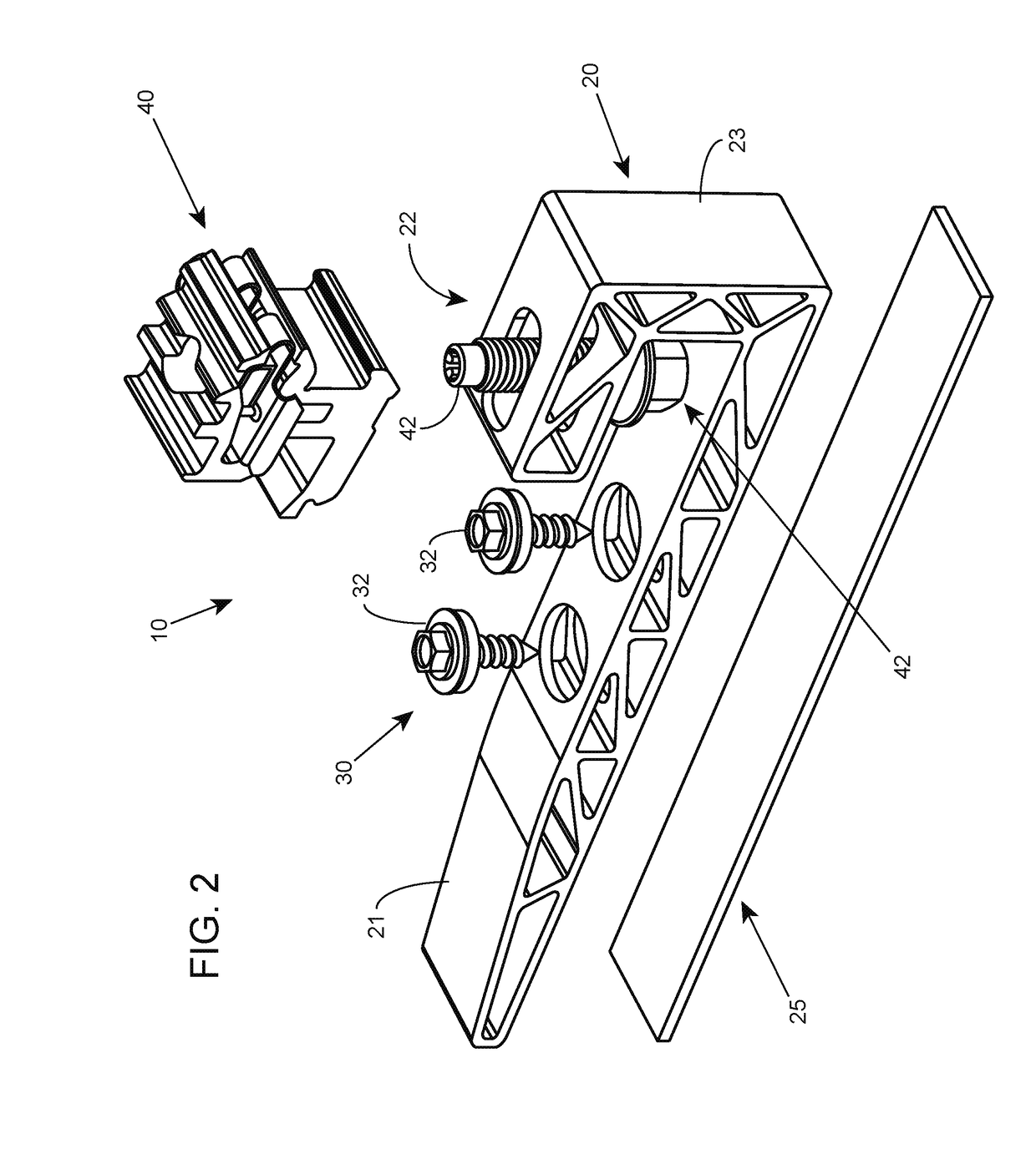
[0034]The present system can provide a mounting assembly for simple installation of photovoltaic module arrays, and is well suited for (but not limited to) use with trapezoidal metal roofs. During installation, the present assembly can be manually snapped onto a first photovoltaic module by an installer holding one end of the module in the air while also holding the present assembly with their other hand. Next, the assembly can be placed on the roof like a kickstand for final adjustment to the desired location before being attached to the roof (while the assembly supports the first module thereon). Next, a second module can be attached onto the PV module connector portion of the assembly. In preferred embodiments, the attachment technique to the first PV module involves rotation of the PV module connector portion into a groove formed in a PV module frame, using the elongated base portion as a torque lever. The attachment technique of the second or subsequent module involves pivoting...


PUM


Abstract

A photovoltaic mounting system having an elongated connector base. The elongated connector base can included photovoltaic module connector portion for supporting a pair of elevated photovoltaic modules above the base. The base may include a captive screw system for holding a pair of mounting screws in place prior to installation and functioning as a screw guide during installation. An assistance clamp fits over the elongated base under the photovoltaic module connector portion to secure the elongated connector base to relatively narrow portion of a roof to provide lateral stability to the elongated connector base.

Description

CROSS-REFERENCES TO RELATED APPLICATIONS[0001]This claims the benefit of U.S. Provisional Application No. 62 / 308,125, filed on Mar. 14, 2016, which is incorporated by reference herein.RELATED APPLICATIONS[0002]This is related to U.S. patent application Ser. No. 14 / 836,807, entitled “Manual Snap-On Photovoltaic Mounting System for Rapid Installation of Photovoltaic Arrays Onto Metal Roofs”, filed Aug. 26, 2015, which claims the benefit of U.S. Provisional Patent Application No. 62 / 171,443, entitled “Manual Snap-On Photovoltaic Mounting System for Rapid Installation of Photovoltaic Arrays Onto Metal Roofs”, filed Jun. 5, 2015; and U.S. Provisional Patent Application No. 62 / 203,822, entitled “Manual Snap-On Photovoltaic Mounting System for Rapid Installation of Photovoltaic Arrays Onto Metal Roofs”, filed Aug. 11, 2015, all of which are incorporated herein by reference in their entirety for all purposes.TECHNICAL FIELD[0003]The present invention relates to mounting photovoltaic arrays....

Claims


Application Information

Patent Timeline
Patent Type & Authority Applications(United States)
IPC IPC(8): H02S20/23F16B5/06F24S23/70
CPCF16B5/0621H02S20/23F24S25/615F24S25/636Y02B10/10Y02B10/20Y02E10/50
Inventor MOLINA, DAVIDFEDOROFF, GEOFFREY JOHN
Owner TESLA INC
Why Eureka
Try Eureka