Vehicle Suspension Control System With High Flow Exhaust Mechanization

Active Publication Date: 2017-09-21
BEIJINGWEST INDUSTRIES
View PDF0 Cites 9 Cited by
  • Summary
  • Abstract
  • Description
  • Claims
  • Application Information

AI Technical Summary

Benefits of technology

[0006]According to another aspect of the disclosure, a method for operating an air management system for a vehicle having a body and plurality of wheels is provided. The method includes providing at least one air spring for interconnecting the body and one of the wheels, a compressor for filling the air spring, a central air line disposed between the air spring and the compressor and fluidly connected to the air spring and the compressor, at least one spring air line extending between the central air line and the air spring, and at least one suspension valve disposed along the spring air line and moveable between an open position and a closed position. The suspension valve allows air to pass between the air spring and the central air line while the suspension valve is in the open position, and the suspension valve inhibits air from passing between the air spring and the central line while the suspension valve is in the closed position. The method further includes providing at least one auxiliary air line extending between the spring air line and the central air line, and at least one high flow exhaust valve disposed along the auxiliary air line being moveable between an open position and a closed position. The high flow exhaust valve allows air to pass between the spring air line and the central air line when the high flow exhaust valve is positioned in the open position, and the high flow exhaust valve inhibits air from passing between the spring air line and the central air line

Problems solved by technology

There are several known issues with current air suspension assemblies.
Notably, they typically can only lower the vehicle at a single speed, and it can take a

Method used


Image

  • Vehicle Suspension Control System With High Flow Exhaust Mechanization
  • Vehicle Suspension Control System With High Flow Exhaust Mechanization
  • Vehicle Suspension Control System With High Flow Exhaust Mechanization

Examples


Example

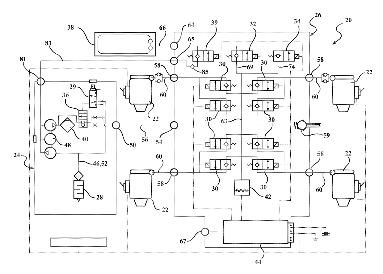
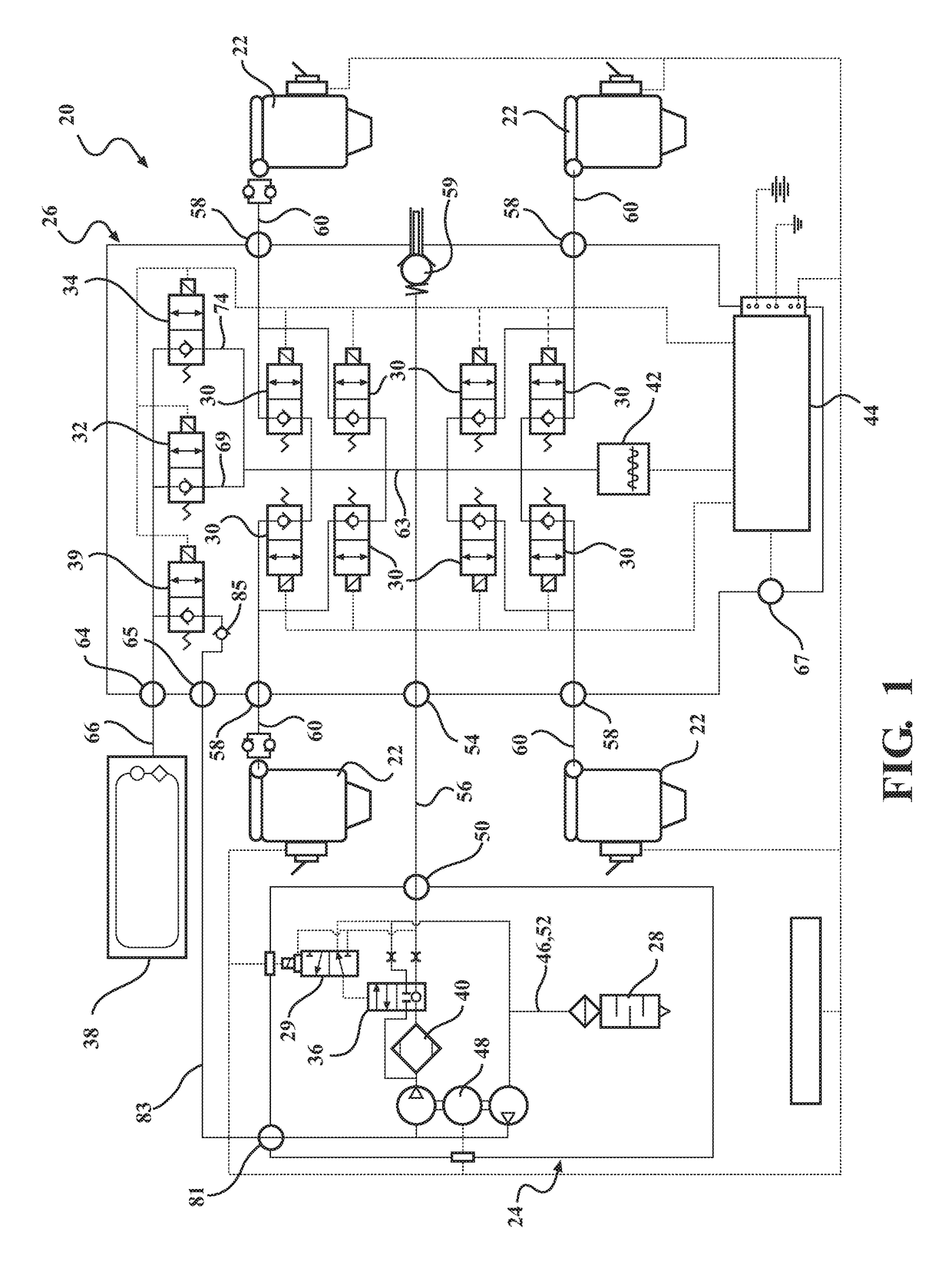
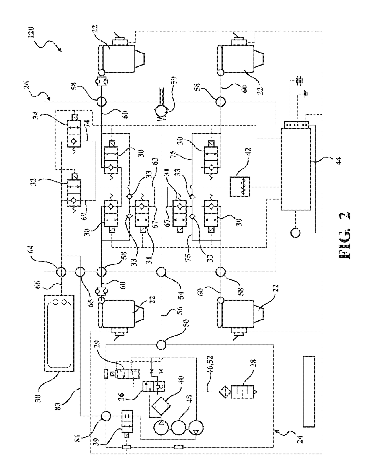
[0022]Referring to the figures, an air management system 20, 120, 220 is generally shown for controlling an air suspension assembly of a vehicle having a body and wheels. In the example embodiment, the subject air management system 20, 120, 220 is described for use on an automobile having four wheels, however, it should be appreciated that it could be utilized on other vehicles having any number of wheels including, but not limited to, motorcycles and all-terrain vehicles.

[0023]As best presented in FIGS. 1, 2 and 11 the air management system 20, 120, 220 is connected to four air springs 22. Each of the air springs 22 interconnect the body and one of the wheels of the vehicle for damping relative forces between the body and the wheels of the vehicle, and for raising and lowering the vehicle to a desired height.

[0024]Generally, the air management system 20 includes a compressor 24 for providing pressurized air for filling the air springs 22, a manifold block 26 having a plurality of v...


PUM


Abstract

An air management system for a vehicle. The air management system includes at least one air spring. A compressor is provided for filling the air spring. A central air line is fluidly connected to the air spring and the compressor. At least one spring air line extends between the central air line and the air spring. At least one suspension valve is disposed along the spring air line. At least one auxiliary air line extends between the spring air line and the central air line. At least one high flow exhaust valve is disposed along the auxiliary air line. At least one isolation check valve is disposed in series with the high flow exhaust along the spring air line. The isolation check valve allows air to pass through therethrough from the air spring to the central air line while preventing air from passing therethrough from the central air line to the air spring.

Description

CROSS REFERENCE TO RELATED APPLICATIONS[0001]This application claims the benefit of U.S. Provisional Patent Application Ser. No. 62 / 310,544 filed on Mar. 18, 2016, and titled “VEHICLE SUSPENSION CONTROL SYSTEM WITH TRANS-AXLE HIGH FLOW EXHAUST MECHANIZATION”, the entire disclosure of which is hereby incorporated by reference.FIELD OF THE INVENTION[0002]An air management system for controlling an air suspension assembly of an automotive vehicle. More specifically, an air suspension control system including high flow exhaust mechanization.BACKGROUND OF THE INVENTION[0003]Air suspension assemblies are known in the art for use on various vehicles, including automobiles. Air suspension assemblies typically include a plurality of air springs, each for interconnecting the body and one of the wheels of the automotive vehicle for damping relative forces between the body and the wheels, and for adjusting the height of the automotive vehicle. One example of such an air suspension assembly is d...

Claims


Application Information

Patent Timeline
IPC IPC(8): B60G17/018B60G17/019B60G17/056B60G11/27B60G11/30
CPCB60G17/018B60G2800/019B60G11/30B60G17/056B60G17/019B60G2202/154B60G2202/42B60G2500/2014B60G2500/2021B60G2500/2044B60G2500/2042B60G2600/73B60G2800/914B60G2400/60B60G2800/164B60G11/27B60G17/0155B60G17/033B60G17/0408B60G17/0521B60G17/0525B60G17/0528B60G2202/152B60G2500/30B60G2206/0116B60G2400/51B60G2500/2012B60G2500/203B60G2600/66
Inventor REUTER, DAVID FREDRICKBORGEMENKE, DANIEL NORBERTRIDDIFORD, BRYAN P.LANDIS, MICHAEL WILLIAM
Owner BEIJINGWEST INDUSTRIES
Why Eureka
Try Eureka