Optical image capturing system

Active Publication Date: 2017-09-21
ABILITY OPTO ELECTRONICS TECH
View PDF1 Cites 10 Cited by
  • Summary
  • Abstract
  • Description
  • Claims
  • Application Information

AI Technical Summary

Benefits of technology

[0007]The aspect of embodiment of the present disclosure directs to an optical image capturing system and an optical image capturing lens which use combination of refractive powers, convex and concave surfaces of five-piece optical lenses (the convex or concave surface in the disclosure denote

Problems solved by technology

It is an important issue to increase t

Method used


Image

  • Optical image capturing system
  • Optical image capturing system
  • Optical image capturing system

Examples


first embodiment

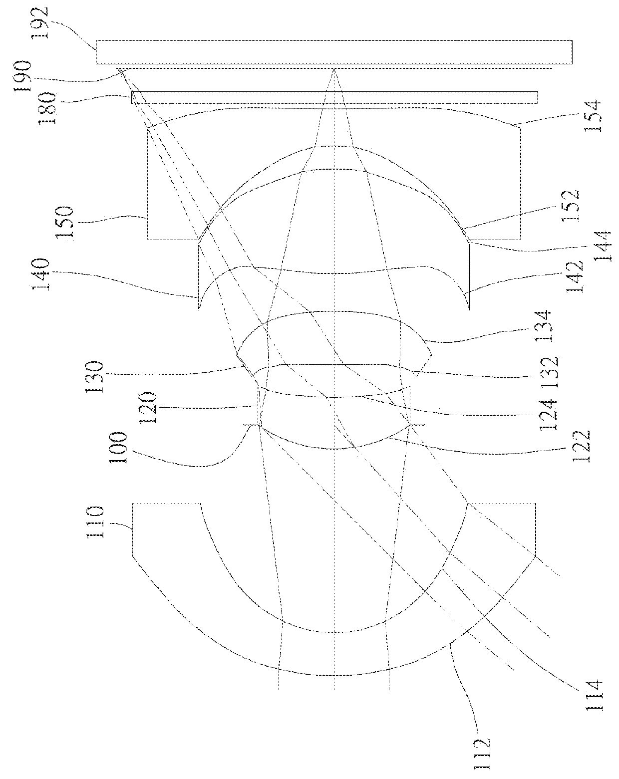
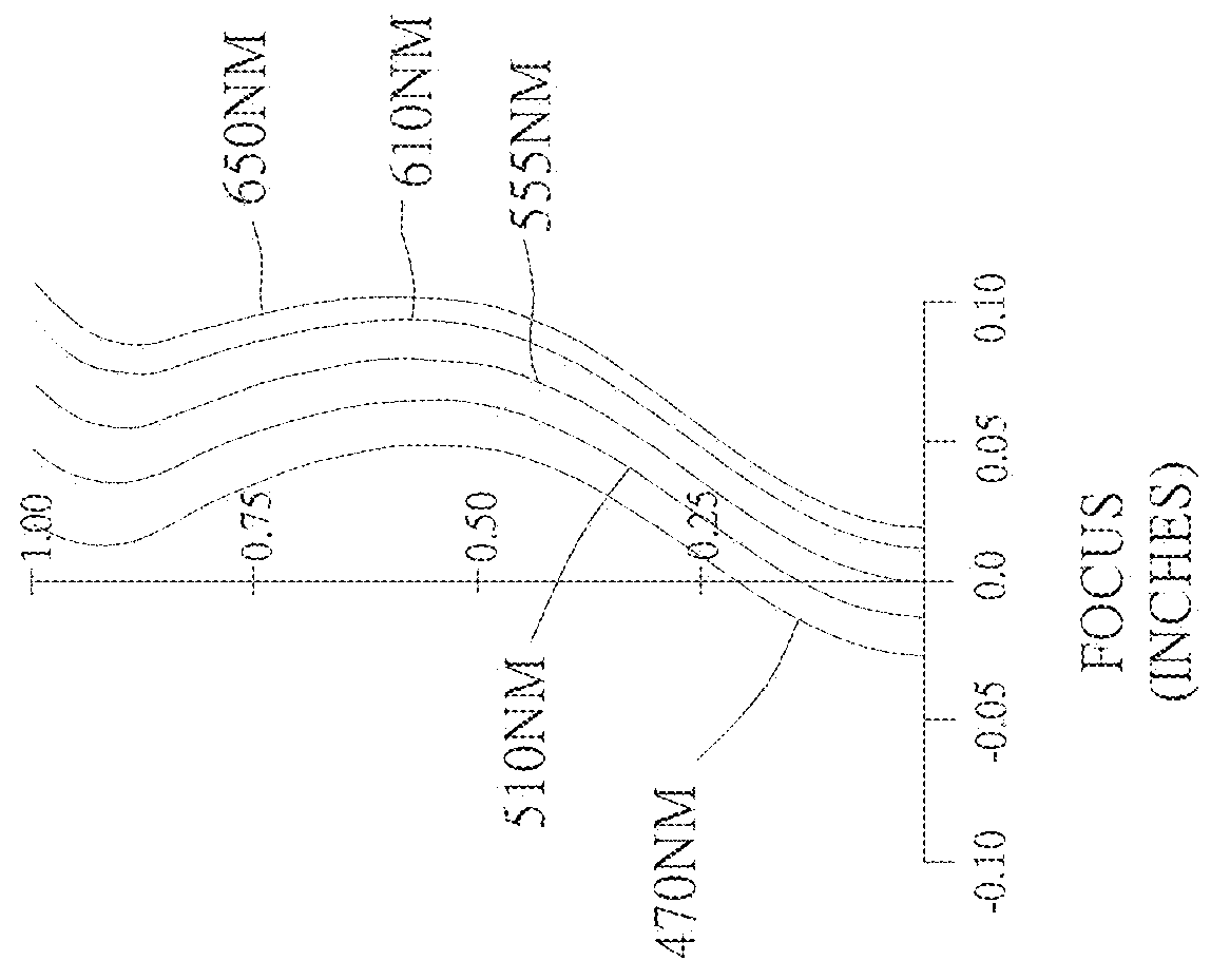
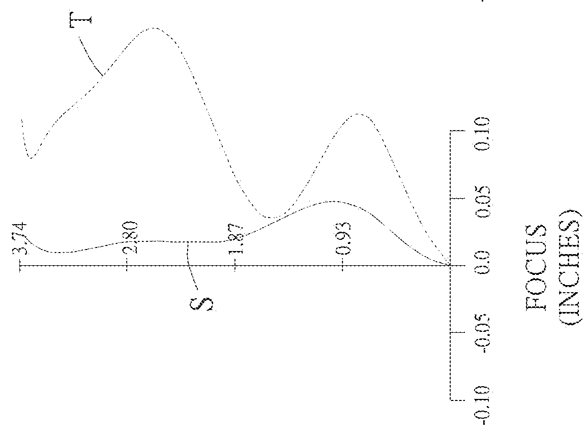
[0105]As shown in FIG. 1A and FIG. 1B, an optical image capturing system 10 of the first embodiment of the present invention includes, along an optical axis from an object side to an image side, a first lens 110, an aperture 100, a second lens 120, a third lens 130, a fourth lens 140, a fifth lens 150, an infrared rays filter 180, an image plane 190, and an image sensor 192. FIG. 1C shows a tangential fan and a sagittal fan of the optical image capturing system 10 of the first embodiment of the present invention, and a transverse aberration diagram at 0.7 field of view when a longest operation wavelength and a shortest operation wavelength pass through an edge of the aperture 100. FIG. 1D is a graphic, showing the relative illuminance of each field of view on the image plane of the optical image capturing system of the first embodiment of the present invention.

[0106]The first lens 110 has negative refractive power and is made of plastic. An object-side surface 112 thereof, which fac...

second embodiment

[0161]As shown in FIG. 2A and FIG. 2B, an optical image capturing system 20 of the second embodiment of the present invention includes, along an optical axis from an object side to an image side, a first lens 210, an aperture 200, a second lens 220, a third lens 230, a fourth lens 240, a fifth lens 250, an infrared rays filter 280, an image plane 290, and an image sensor 292. FIG. 2C is a transverse aberration diagram at 0.7 field of view of the second embodiment of the present invention. FIG. 2D is a graphic, showing the relative illuminance of each field of view on the image plane of the optical image capturing system of the second embodiment of the present invention.

[0162]The first lens 210 has positive refractive power and is made of plastic. An object-side surface 212 thereof, which faces the object side, is a convex aspheric surface, and an image-side surface 214 thereof, which faces the image side, is a concave aspheric surface. The object-side surface 212 and the image-side ...

third embodiment

[0173]As shown in FIG. 3A and FIG. 3B, an optical image capturing system of the third embodiment of the present invention includes, along an optical axis from an object side to an image side, an aperture 300, a first lens 310, a second lens 320, a third lens 330, a fourth lens 340, a fifth lens 350, an infrared rays filter 380, an image plane 390, and an image sensor 392. FIG. 3C is a transverse aberration diagram at 0.7 field of view of the third embodiment of the present invention. FIG. 3D is a graphic, showing the relative illuminance of each field of view on the image plane of the optical image capturing system of the third embodiment of the present invention.

[0174]The first lens 310 has positive refractive power and is made of plastic. An object-side surface 312 thereof, which faces the object side, is a convex aspheric surface, and an image-side surface 314 thereof, which faces the image side, is a convex aspheric surface. The object-side surface 312 has an inflection point.

[0...


PUM


Abstract

An optical image capturing system includes, along the optical axis in order from an object side to an image side, a first lens, a second lens, a third lens, a fourth lens, and a fifth lens. At least one lens among the first to the fifth lenses has positive refractive power. The fifth lens can have negative refractive power, wherein both surfaces thereof are aspheric, and at least one surface thereof has an inflection point. The lenses in the optical image capturing system which have refractive power include the first to the fifth lenses. The optical image capturing system can increase aperture value and improve the imaging quality for use in compact cameras.

Description

BACKGROUND OF THE INVENTION[0001]1. Technical Field[0002]The present invention relates generally to an optical system, and more particularly to a compact optical image capturing system for an electronic device.[0003]2. Description of Related Art[0004]In recent years, with the rise of portable electronic devices having camera functionalities, the demand for an optical image capturing system is raised gradually. The image sensing device of the ordinary photographing camera is commonly selected from charge coupled device (CCD) or complementary metal-oxide semiconductor sensor (CMOS Sensor). In addition, as advanced semiconductor manufacturing technology enables the minimization of the pixel size of the image sensing device, the development of the optical image capturing system towards the field of high pixels. Therefore, the requirement for high imaging quality is rapidly raised.[0005]The conventional optical system of the portable electronic device usually has three or four lenses. Ho...

Claims


Application Information

Patent Timeline
IPC IPC(8): G02B13/00G02B27/00G02B9/60G02B5/00G02B5/20
CPCG02B13/0045G02B5/005G02B27/0025G02B9/60G02B5/208G02B13/18
Inventor LAI, CHIEN-HSUNLIU, YAO-WEICHANG, YEONG-MING
Owner ABILITY OPTO ELECTRONICS TECH
Why Eureka
Try Eureka