Dirt removing device and dirt removing unit

a dirt removal device and dirt removal technology, applied in road cleaning, cleaning equipment, carpet cleaners, etc., can solve the problems of unstable beating force and beating speed, inability to use detergents, and different degree of decontamination, so as to improve the effect of removing dirt, easy replacement, and easy removal of incrustation

Inactive Publication Date: 2017-09-28
HAIER ASIA INT CO LTD +1
View PDF5 Cites 2 Cited by
  • Summary
  • Abstract
  • Description
  • Claims
  • Application Information

AI Technical Summary

Benefits of technology

[0014]According to the above described disclosure, the vibration unit causes, by means of supplying power, the cassette mechanism to vibrate in the direction substantially orthogonal with the beating face of the head, the head can automatically perform an action of beating the dirt and removing objects. As a result, the beating force and the beating speed are homogeneous and the hands are required to move quickly, the hands will not be tired even if the dirt removing operation is performed for a long time. In addition, since the cassette mechanism can be attached and detached from the device body, it is possible to install, on the device body, a cassette mechanism accommodating a liquid corresponding to the state of the dirt, and to change the type of the liquid according to the state of the dirt portion, by means of, for example, preparing in advance a plurality of cassette mechanisms each accommodating a different kind of liquid, respectively, in the liquid accommodating portion, thereby improving the effect of removing dirt.
[0015]In particular, according to the present disclosure, the head potion is detachable from the cassette mechanism, and the liquid accommodating portion is composed of an accommodating portion body and a cover member. The liquid can be supplied to the liquid accommodating space or the liquid in the liquid accommodating portion can be easily replaced with other kind of liquid, by means of removing the cover member form the accommodating portion body, so that the dirt removing device can be repeatedly used multiple times. In this case, since the liquid supplying, replacement and the like can be performed in a state in which the liquid accommodating portion is removed from the device body, the device body will not be wetted by the liquid when supplying liquid and the device body is not required to be subjected to a waterproof treatment. In addition, the inside of the liquid accommodating portion can be cleaned by disassembling the liquid accommodating portion into the accommodating portion body and the cover member, thereby easily removing the incrustation, the c

Problems solved by technology

Nevertheless, the dirt removing system of Non-Patent Document 1 has a problem that a beating force and a beating speed are unstable and the degree of decontamination is different or the hand fatigue is caused, since dirt removing actions are performed with a hand holding the bottle b

Method used


Image

  • Dirt removing device and dirt removing unit
  • Dirt removing device and dirt removing unit
  • Dirt removing device and dirt removing unit

Examples


embodiment i

[0030]Hereinafter, embodiment I of the present disclosure will be described with reference to accompanying drawings.

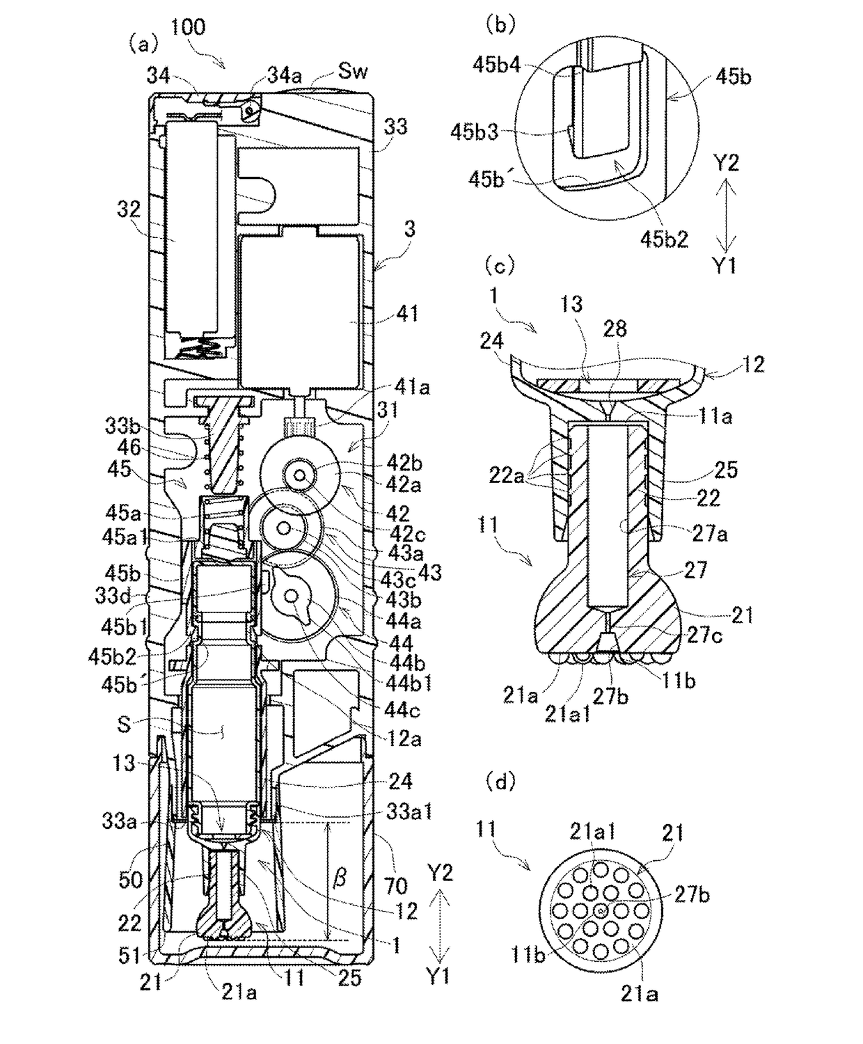
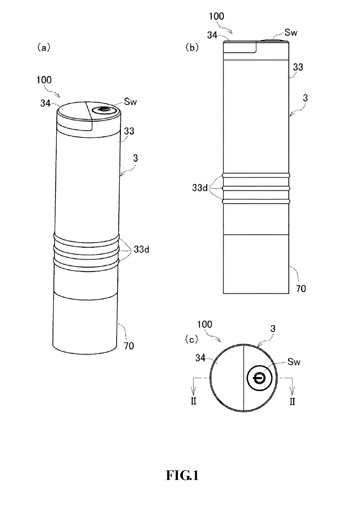
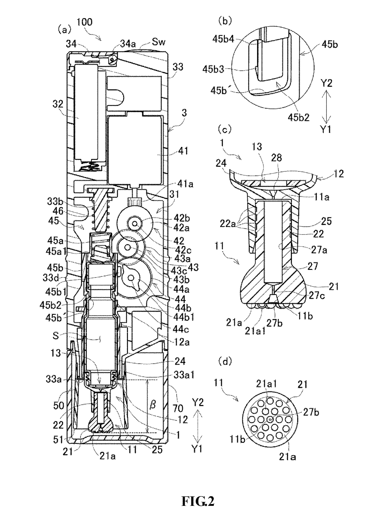
[0031]FIGS. 1 and 2 are views showing a dirt removing device 100 according to embodiment I of the present disclosure. Specifically, FIG. 1(A) is a perspective view showing the dirt removing device 100 according to the present embodiment. FIG. 1(B) is a side view showing the dirt removing device 100. FIG. 1(C) is a top view showing the dirt removing device 100. In addition, FIG. 2(A) is a longitudinal section view of the dirt removing device 100 along a section line II-II in FIG. 1(C). FIG. 2(B) is a perspective view showing a part of the dirt removing device 100, that is, a part in the vicinity of an engaging claw 45b2. FIG. 2(C) is an enlarged longitudinal section view showing a part of a liquid accommodating portion 12 and a head 11 shown in FIG. 2(A). FIG. 2(D) is a bottom view of the head 11.

[0032]As shown in FIG. 2(A), the dirt removing device 100 includes: a devi...

embodiment ii

[0086]FIG. 7 shows a part of a cassette mechanism 20 that constitutes embodiment II (that is, a dirt removing device 120) of the present disclosure. Specifically, FIG. 7 is a perspective view showing a part of a liquid accommodating portion 7 and a head 8. FIG. 7(A) shows the cassette mechanism 20 before the head 8 is inserted into the liquid accommodating portion 7. FIG. 7(B) shows the cassette mechanism 20 after the head 8 is inserted into the liquid accommodating portion 7. The dirt removing device 120 of the present embodiment is different from embodiment I in that the dirt removing device 120 has a liquid amount adjustment portion 9 for adjusting the drop amount of the liquid. Hereinafter, embodiment II is the same as embodiment I except for the structure described later, and the description of the same structure will be omitted. In addition, for easy description, although it is not shown in the drawings that the liquid storage portion 71 of the liquid accommodating portion 7 h...

embodiment iii

[0092]FIG. 9 is a longitudinal section view showing a dirt removing unit 130 according to embodiment III of the present invention. FIG. 10 is an exploded view showing a heating device 101 constituting the dirt removing unit 130 shown in FIG. 9. The dirt removing unit 130 of the present embodiment shown in FIG. 9 is composed of the dirt removing device 100 of embodiment I and the heating device 101.

[0093]As shown in FIG. 10, the heating device 101 includes a member 103 for arranging an absorbing pad (a cover for arranging an absorbing pad), a device body cover 105, a decorative panel 107, a heating plate 109, a first heat insulating material 111, a heater 113, a second heat insulating material 115 and a heating device body 117.

[0094]The member 103 for arranging an absorbing pad and the device body cover 105 are circular members in which opening portions 103a and 105a are formed at the centers, respectively. The member 103 for arranging an absorbing pad rotates in a state in which an ...


PUM


Abstract

A dirt removing device including: a cassette mechanism having a head formed with a beating face, a liquid accommodating portion for accommodating liquid, and a water supplying passage which is started from the liquid accommodating portion and penetrates into the entire head; and a device body having a vibration unit. The cassette mechanism is detachably received in the vibration unit, and the vibration unit, when being powered, causes the cassette mechanism to vibrate in a direction substantially orthogonal with the beating face of the head. The liquid is supplied from the liquid accommodating portion to the beating face of the head through the water supplying passage, along with the vibration of the cassette mechanism caused by the vibration unit.

Description

TECHNICAL FIELD[0001]The present disclosure relates to a dirt removing device and a dirt removing unit, which are capable of beating and washing a local part of a cloth product, providing liquid to a dirt portion on the cloth product and exerting a beating force automatically, and can also replace the used liquid.BACKGROUND[0002]In the case that feculence is adhered to a local part of the cloth product to become the dirt, in view of convenience and efficiency of washing off the dirt, it is better to only washing a dirt part compared with washing the entire cloth product. An apparatus for locally washing the cloth product can be exemplified by a dirt removing system of Non-Patent Document 1.[0003]The dirt removing system of Non-Patent Document 1 is composed of a bottle body for containing a detergent and an absorbing sheet, and a fine hole for providing the detergent is formed at a top end of the bottle body. The dirt removing system is capable of beating the dirt part through the to...

Claims


Application Information

Patent Timeline
IPC IPC(8): D06F43/00A47L11/40A47L11/38D06F7/04A47L11/30
CPCD06F43/002D06F7/04E01H1/103A47L11/38A47L11/4069A47L11/30A47L25/00A47L25/08
Inventor FUJIWARA, MASAHIROYAMAMOTO, MASAKAZUNORO, MASARU
Owner HAIER ASIA INT CO LTD
Why Eureka
Try Eureka