Supercharge Your Innovation With Domain-Expert AI Agents!

Flange gasket

a gasket and flange technology, applied in the field of gaskets, can solve the problems easy cracking and fatigue of materials if not loaded, etc., and achieve the effects of low rigidity, low rigidity, and easy installation

Inactive Publication Date: 2017-09-28
LGC US ASSET HLDG LLC
View PDF6 Cites 4 Cited by
  • Summary
  • Abstract
  • Description
  • Claims
  • Application Information

AI Technical Summary

Benefits of technology

The present invention is a hybrid gasket that combines the benefits of a corrugated metal gasket and a kammprofile gasket. It eliminates the disadvantages of both and provides increased rigidity, improved handling characteristics, and better recovery and resilience. The gasket has a high load bearing capability and is adaptable to alignment deficiencies. It also generates higher stress point contacts. This is achieved through machining operations and the use of an alternating series of machined corrugations that improves recovery and resilience. Overall, the gasket is a new construction that combines the advantages of both styles and eliminates their disadvantages.

Problems solved by technology

Disadvantages of a corrugated metal gasket include the following:1. Moderate to low load bearing capability which results in the material being prone to cracking and fatigue if not loaded evenly.2. Low rigidity and therefore difficult to handle.3. Only applicable to 150 and 300 class flanges.
Low rigidity can be a disadvantage as its more fragile nature can allow over-bending which in turn can damage the graphite (or ptfe) facing.

Method used


Image

  • Flange gasket
  • Flange gasket
  • Flange gasket

Examples


Embodiment Construction

[0044]For the purposes of promoting an understanding of the disclosure, reference will now be made to the embodiments illustrated in the drawings and specific language will be used to describe the same. It will nevertheless be understood that no limitation of the scope of the disclosure is thereby intended, such alterations and further modifications in the illustrated device and its use, and such further applications of the principles of the disclosure as illustrated therein being contemplated as would normally occur to one skilled in the art to which the disclosure relates.

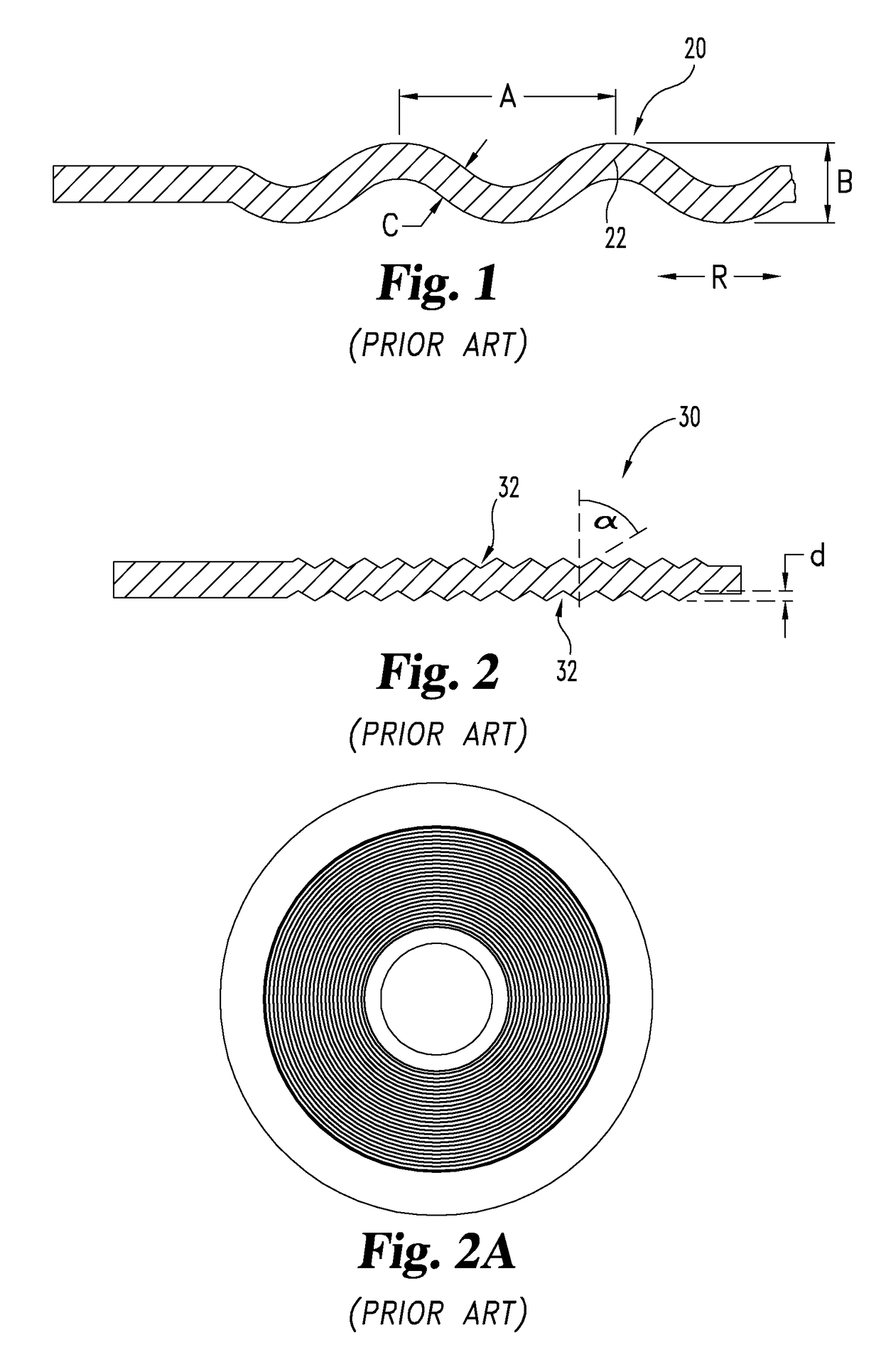
[0045]Referring first to FIG. 1, a prior art style of annular flange gasket 20 for use in a bolted flange joint is illustrated in partial, cross-sectional form. The focus of FIG. 1 is on the cross-sectional shape of the corrugations 22 which have a generally sinusoidal shape in a radial direction. The letter “R” reference with arrows are added to FIG. 1 to show the radial direction. This style of gasket is typica...


PUM


Abstract

A corrugated metal gasket for use between two flanges wherein the corrugated metal gasket is produced by a method comprising the steps of providing an annular gasket substrate and machining into that substrate a plurality of substantially uniform and generally concentric corrugations.

Description

CROSS REFERENCE TO RELATED APPLICATION[0001]This application is a continuation of U.S. Ser. No. 13 / 795,897 filed Mar. 12, 2013, which claims the benefit of U.S. Provisional Application No. 61 / 615,441 filed Mar. 26, 2012 which are hereby incorporated by reference.BACKGROUND OF THE INVENTION[0002]The present invention relates generally to gaskets and, more particularly, to an improved gasket for positioning between facing conduit flanges. These facing flanges are bolted together and some of the bolted joint characteristics are relevant to the type of gasket which is selected. In terms of technological background, one general style of flange gasket is best described as a corrugated metal gasket. One example of such a corrugated metal gasket is disclosed in U.S. Pat. No. 5,421,594, which issued Jun. 6, 1995 to Marine & Petroleum Mfg., Inc. of Houston, Tex. Another general style of flange gasket is best described as a kammprofile gasket whose design and construction are covered by standa...

Claims


Application Information

Patent Timeline
Patent Type & Authority Applications(United States)
IPC IPC(8): F16J15/08F16L23/18F16L23/20
CPCF16J15/0818F16L23/20F16J15/0806F16L23/18
Inventor KOLB, STEVEN KRISTOPHER
Owner LGC US ASSET HLDG LLC
Features
  • R&D
  • Intellectual Property
  • Life Sciences
  • Materials
  • Tech Scout
  • Unparalleled Data Quality
  • Higher Quality Content
  • 60% Fewer Hallucinations
Learn More