Metal frame for device being equipped with wireless charging transmitter or receiver

Inactive Publication Date: 2017-09-28
KIM JAE BEOM
View PDF0 Cites 0 Cited by
  • Summary
  • Abstract
  • Description
  • Claims
  • Application Information

AI Technical Summary

Benefits of technology

[0014]A technical object of the present invention is to provide a metal frame for a device being equipped with a wireless charging transmitter or receiver capable of performing wireless charging by including at least a wireless charging receiver, i.e., enabling wireless charging to be carried out smoothly despite, for example, a mobile device having its outer feature equipped with a metal frame instead of a plastic frame, wherein the metal frame provid

Problems solved by technology

Therefore, it has become more difficult for the manufacturers to create their own distinguished functions that are related to the performance of the device.
Accordingly, the manufacturers are becoming more focused on the design of their mobile devices, and, therefore, the selection of the material for a frame configuring the outside feature of the mobile device has become one of the most important issues.
However, due to the characteristics of the plastic material, there were limitations in realizing high-quality texture in the mobile devices.
Evidently, metal frames may be disadvantageous in the aspect of weight as compared to the plastic frames.
However, due to the exc

Method used


Image

  • Metal frame for device being equipped with wireless charging transmitter or receiver
  • Metal frame for device being equipped with wireless charging transmitter or receiver
  • Metal frame for device being equipped with wireless charging transmitter or receiver

Examples


Example

[0037]Hereinafter, the exemplary embodiments of the present invention will be illustrated in the appended drawings and described in detail in the detailed description of the present invention. In describing the present invention, when it is determined that the detailed description on a related disclosed technology may cause ambiguity in the concept (or idea) of the present invention, the detailed description of the same will be omitted for simplicity.

[0038]The terms used in the description of the present invention are defined based on their corresponding functions within the present invention. And, since the meaning of such terms may vary in accordance with the intentions or practices of anyone skilled in the art, the definition of the terms used in the description of the present invention should be understood based on the overall context of this specification.

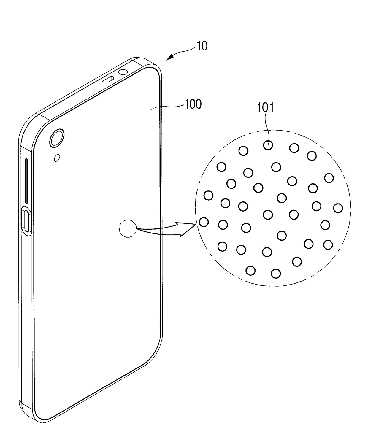
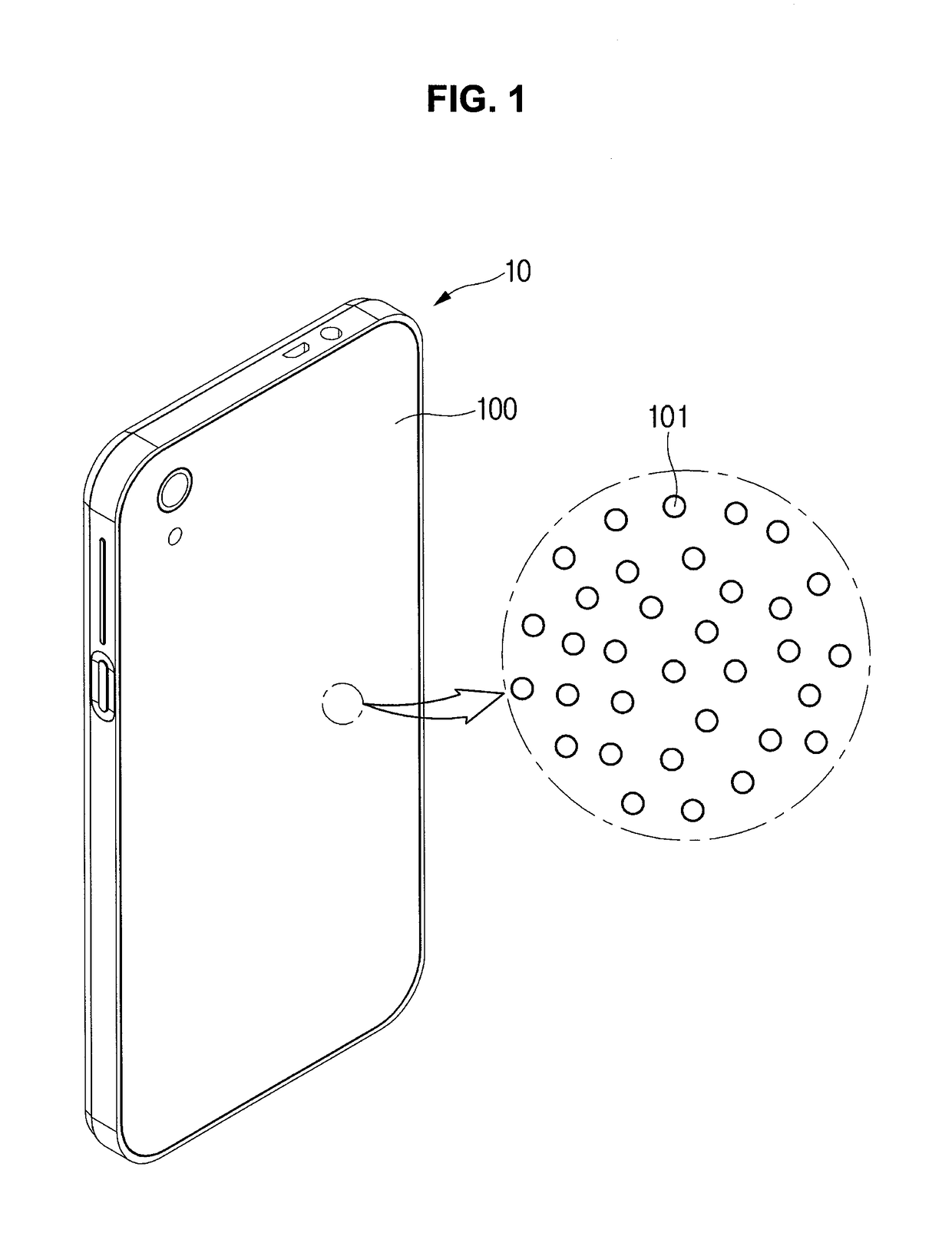
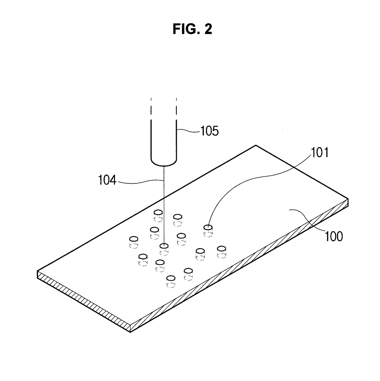
[0039]Although the metal frame mentioned in the present invention may mainly correspond to a finishing frame (outer cover) c...


PUM


Abstract

Disclosed herein is a metal frame for a device being equipped with a wireless charging transmitter or receiver including a plurality of perforation holes configured in at least one partial area of the metal frame, wherein the perforation hole has a diameter ranging from sub nm to several μm, and wherein an average distance between an arbitrary point A on a circumferential surface of a perforation hole, among the plurality of perforation holes, and an arbitrary point B on a circumferential surface of another perforation hole being adjacent to the perforation hole is equal to or less than a skin depth corresponding to a metallic material of the metal frame, and wherein point A and point B respectively correspond to points indicating a longest distance between the circumferential surfaces of each perforation hole to which point A and point B belong.
Accordingly, the metal frame is expected to perform wireless charging by including at least a wireless charging receiver, i.e., enabling wireless charging to be carried out smoothly despite equipping a mobile device with a metal frame for its outer feature instead of a plastic frame, wherein the metal frame provides an excellent texture of premium quality and outstanding durability as compared to the plastic frame.

Description

CROSS-REFERENCE TO RELATED APPLICATIONS[0001]This application claims priority from Korean Patent Application No. 10-2016-0033939 filed on Mar. 22, 2016, in the Korean Intellectual Property Office, the disclosure of which is incorporated herein by reference in its entirety.BACKGROUND OF THE INVENTION[0002]Field of the Invention[0003]The present invention relates to a metal frame for a device equipped with a wireless charging transmitter or receiver and, most particularly, to a metal frame for a device being equipped with a wireless charging transmitter or receiver including a plurality of perforation holes configured in at least one partial area of the metal frame, wherein the perforation hole has a diameter ranging from sub nm to several μm, and wherein an average distance between an arbitrary point A on a circumferential surface of a perforation hole, among the plurality of perforation holes, and an arbitrary point B on a circumferential surface of another perforation hole being ad...

Claims


Application Information

Patent Timeline
IPC IPC(8): H04B1/3888
CPCH04B1/3888H04M1/185H04M19/08H04M1/0202H02J50/00
Inventor KIM, JAE BEOM
Owner KIM JAE BEOM
Why Eureka
Try Eureka