Developing roller and image forming method using the same

Inactive Publication Date: 2008-09-11
KONICA MINOLTA BUSINESS TECH INC
View PDF38 Cites 11 Cited by
  • Summary
  • Abstract
  • Description
  • Claims
  • Application Information

AI Technical Summary

Benefits of technology

[0056]It is supposed that non-Newtonian fluid property is given to the coating liquid by the inorganic oxide particles when the size and the content of the inorganic oxide particles are within the above ranges so that the sedimentation of the resin particles 13 is inhibited and the coating can be carried out while maintaining the uniform dispersed state. When the size of the inorganic oxide particles is less than 5 nm, the particles is not homogeneously dispersed and coagulated in the coating liquid so that the inorganic oxide particles cannot assist dispersion of the resin particles and the releasing of the particles is caused. When the size of the inorganic oxide particles exceeds 100 nm, the non-Newtonian fluid property is not given to the coating liquid and the sedimentation of the resin particles in the coating liquid cannot be prevented. When the content of the inorganic oxide is less than 1% by weight, the viscosity of the coating liquid cannot be raised no longer, and when the content exceeds 40% by weight, the inorganic oxide particles are neared and coagulated with together and so that the effects of the invention cannot be realized.
[0057]The diameter of the inorganic oxide particles is a number based average primary particle diameter. In concrete, 100 particles are randomly observed by the transmission electron microscope with a magnitude of 100,000 times as the primary particle and Fere diameter in the horizontal direction is calculated and defined as the number average primary particle diameter as the same as the measurement of the diameter of the resin particles. When plural kinds of the inorganic oxide particles are used, 100 particles of each of the kinds of the particles are observed by the above procedure and the number average diameter of each kind of the inorganic oxide particles is determined.
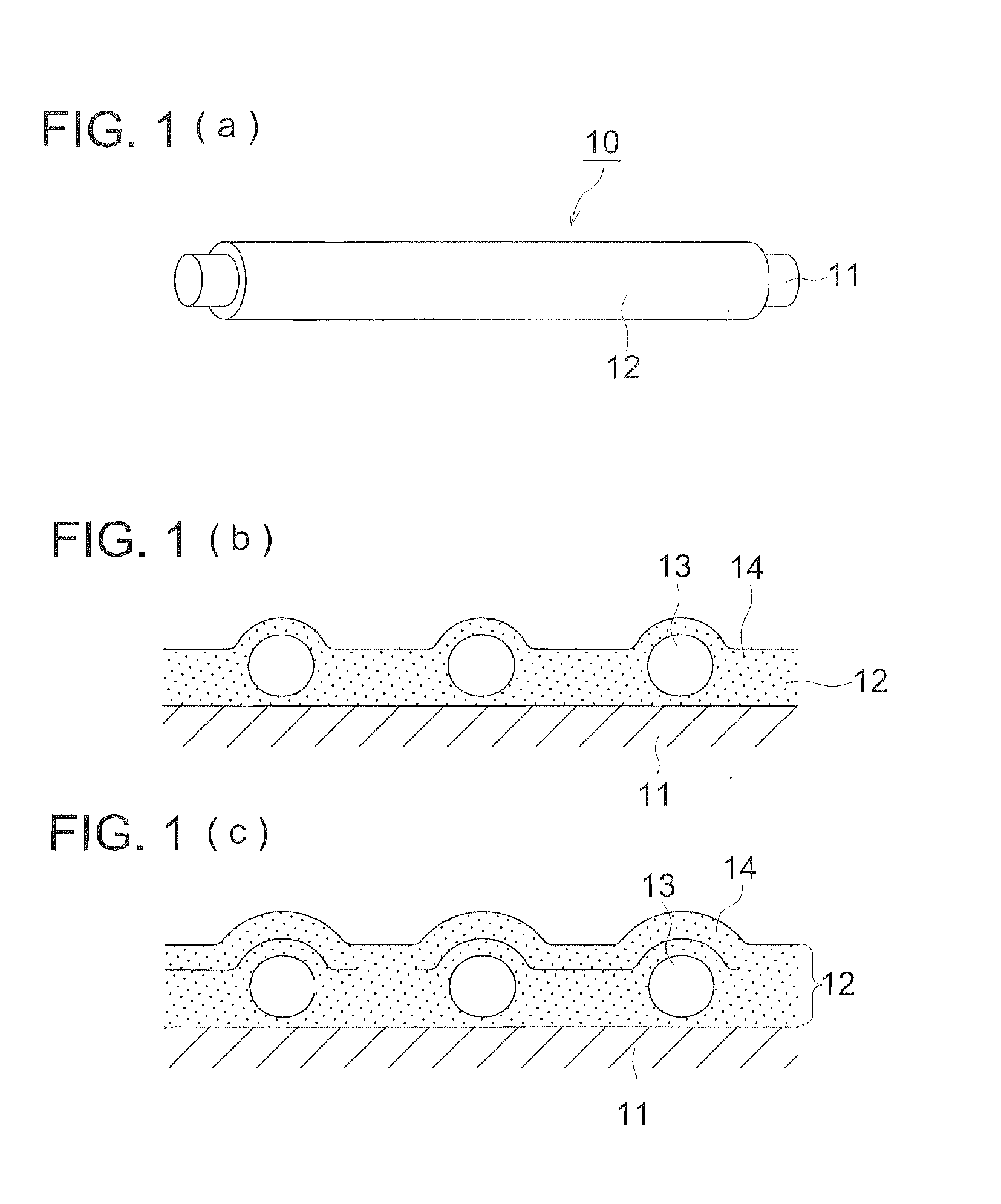
[0058]The relation of the resin particles and the inorganic oxide particles usable in the invention is described below. The resin particles 13 and the inorganic oxide particles 14 have the relation that the diameter of the resin particles 13 is from 50 to 4,000 times as large as the average diameter of the inorganic oxide particles. Namely, the diameter of the resin particles 13 contained in the resin layer 12 is from 50 to 4,000 times, preferably from 50 to 1,000 times, and more preferably from 100 to 400 times as large as average diameter of the inorganic oxide particles 14. Also, the resin particles 13 and the inorganic oxide particles 14 have the relation that number based average primary particle diameter of the resin particles 13 is from 50 to 4,000 times preferably from 50 to 1,000 times, and more preferably from 100 to 400 times as large as average diameter of the inorganic oxide particles 14.
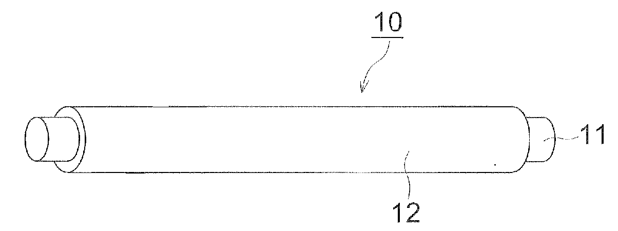
[0059]When the coating liquid satisfying the above relation is coated on the shaft 11, the coating can be smoothly carried out by the effect of the non-Newtonian fluid property thereof. It is presumed that the coated layer is formed while the resin particles 13 are suitably dispersed state after the coating by the effect of the non-Newtonian fluid property so as that the resin layer 12 can be formed, in which the resin particles are homogeneously dispersed. It is also presumed that the sedimentation of the resin particles 13 in the coating liquid by the weight themselves is avoided by the non-Newtonian fluid property caused by the inorganic oxide particles and the homogeneous dispersion of the resin particles 13 in the coating liquid can be maintained. By such the action, the resin layer 12 in which the rein particles are homogeneously dispersed is formed on the shaft 11. Therefore, it is considered that the transportation amount of the toner by thus prepared developing roller has not partiality and uniformly charging can be carried out so that the suitable toner images without density unevenness can be obtained.
[0060]The content of the resin particles 13 in the resin layer 12 is within the range of from 0.25 to 2.50 times of that of the inorganic oxide particles 14. Namely, the content of the resin particles 13 is from om25 to 2.50 times, preferably from 0.25 to 2.00, and more preferably from 0.50 to 1.50 times of that of the inorganic oxide particles. Sufficient transportation and charging can be performed by the roller surface of thus prepared developing roller when the contents of them satisfy the above relation. Consequently, suitable images without ununiformity in the density can be stably formed. It is considered that the suitable dispersion state without coagulation of the resin particles can be obtained in the coating liquid by the effect of the non-Newtonian fluid property so that the coating liquid can he coated on the shaft 11 while maintaining the suitable dispersion state of the resin particles 13.
[0061]The resin layer forms the toner layer on the surface thereof and gives charge by triboelectricity. Moreover, strong adhesion force is required between the resin layer 12 and the shaft 11.

Problems solved by technology

Suitable image formation is difficultly continued for long period by releasing the particles when the developer roller given roughness by the addition of the particles is used.
As a result of that, a portion where the designated amount of the toner is not supplied occurs so that a printed image having unevenness in the density is formed.
As above-described, the developing roller having the resin layer containing the particles causes the problem of the releasing of the particles.
However, concrete countermeasure for solving such the problem is almost not taken.
It is difficult to perform stable image formation without image defect, particularly in the image formation by the non-image one-component method in which pressure is applied on the developing roller.

Method used


Image

  • Developing roller and image forming method using the same
  • Developing roller and image forming method using the same
  • Developing roller and image forming method using the same

Examples


examples

[0112]The embodiment of the invention is concretely described below referring examples though the invention is not limited to the examples.

1. Preparation of Developing Roller

[0113]Developing Rollers 1 to 28 were prepared according to the following procedure.

(1) Preparation of Developing Roller 1Furnace Black 30 parts by weightAnatase type titanium oxide particle (Number based8.5 parts by weightaverage primary particle diameter: 35 nm, treated bymethylhydrogenpolysiloxane on the surface)Methyl ethyl ketone(MEK)400 parts by weight 

[0114]The above materials were charged in the above order into a media type dispersing machine Dyno-Mill TILAB, manufactured by Shinmaru Enterprises Corp., and 100 parts by weight of glass beads having a diameter of 0.5 mm were further added, and the resultant mixture was subjected to dispersing treatment for 2 hours at 1,000 rpm to prepare a primary dispersion.

[0115]After that, 100 parts by weight of urethane resin, Nippolan 5120 manufactured by Nippon Poly...


PUM


Abstract

A developing roller for electrophotographic image forming apparatus is disclosed. The developing roller has a shaft and a resin layer, and the resin layer comprises a binder resin, a resin particle having a particle diameter of 5 μm to 30 μm and a content of from 10% to 50% by weight with respect to the resin layer, and inorganic oxide particles having a number based average primary particle diameter of 5 nm to 100 nm and a content of 1% to 40% by weight with respect to the resin layer. An image forming method employing the developer roller is also disclosed.

Description

[0001]This application is based on Japanese Patent Application No. 2007-059780 filed on Mar. 9, 2007, in Japanese Patent Office, the entire content of which is hereby incorporated by reference.TECHNICAL FIELD[0002]The present invention relates to a developing roller to be used for electrophotographic image forming apparatuses such as copying machines, printers and facsimile receiving machines, and particularly relates to a developing roller composed of a shaft and a resin layer containing particles provided on the shaft and to an image forming method using the developing roller.TECHNICAL BACKGROUND[0003]In usual image forming method by electrophotographic system, a toner image is formed on an image receiving sheet by the following procedure. An electrostatic image formed on an image carrier, typically an electrophotographic photoreceptor, is developed by supplying an electrically charged toner. The toner image formed on the image carrier formed by developing is transferred onto an i...

Claims


Application Information

Patent Timeline
IPC IPC(8): G03G13/16G03G15/08
CPCG03G15/0818
Inventor UCHINO, SATOSHIANNO, MASAHIROOSHIBA, TAKEOOKUYAMA, OKUSHIOBARA, SHINYAHIRAMOTO, RYUICHIMATSUYA, SO
Owner KONICA MINOLTA BUSINESS TECH INC
Why Eureka
Try Eureka