Patient interface device for laser eye surgery having light guiding structure for illuminating eye

a patient interface and laser eye surgery technology, applied in laser surgery, medical science, diagnostics, etc., can solve the problems of difficult to join all the pieces together to fix the position of the patient's eye, difficulty in achieving and ensuring such a high degree of parallelism, and difficulty in using such vacuum lines

Active Publication Date: 2017-10-05
AMO DEVMENT
View PDF5 Cites 8 Cited by
  • Summary
  • Abstract
  • Description
  • Claims
  • Application Information

AI Technical Summary

Benefits of technology

[0003]Laser surgery has become an important technique for the treatment of vision problems. It is necessary to stabilize the patient's eye of a patient during laser surgery in a predetermined position relative to the focal point of the laser beam, by physically constraining eye movement with respect to the laser beam during such laser surgery.

Problems solved by technology

In general, existing patient interface devices are comprises of multiple pieces, and it can be difficult to join all the pieces together to fix the position of the patient's eye with respect to the laser surgery apparatus, especially if one part is already in contact with the patient and the other part is connected to the laser surgery apparatus.
However, the connection process typically requires the patient to comply with various commands by the physician or physician's assistant, which may be difficult because the patient is often nervous and under sedation.
In general, the use of such vacuum lines is often awkward and unwieldy.
Achieving and ensuring such a high degree of parallelism is further complicated when the patient interface device comprises two or more parts which must be fitted and connected together.
High manufacturing tolerances may be required which can increase cost and complexity.
However existing patient interface devices make it difficult to reliably and precisely deliver a desired amount of light to the vicinity of the patient's eye.
Often times glare from the illuminating light source can impede a clear view of the surgical area.
Other times not enough light is delivered to the vicinity of the patient's eye, producing captured images of the surgical area which are overly dark and difficult to see.

Method used


Image

  • Patient interface device for laser eye surgery having light guiding structure for illuminating eye
  • Patient interface device for laser eye surgery having light guiding structure for illuminating eye
  • Patient interface device for laser eye surgery having light guiding structure for illuminating eye

Examples


Embodiment Construction

[0046]Exemplary embodiments of laser surgery systems and eye stabilization devices are described below to illustrate various aspects and advantages of these devices and methods are described below. However, it should be understood that the principles involved in these devices and methods can be employed in a variety of other contexts, and therefore the novel devices and method disclosed and claimed here should not be construed as being limited to the example embodiments described below.

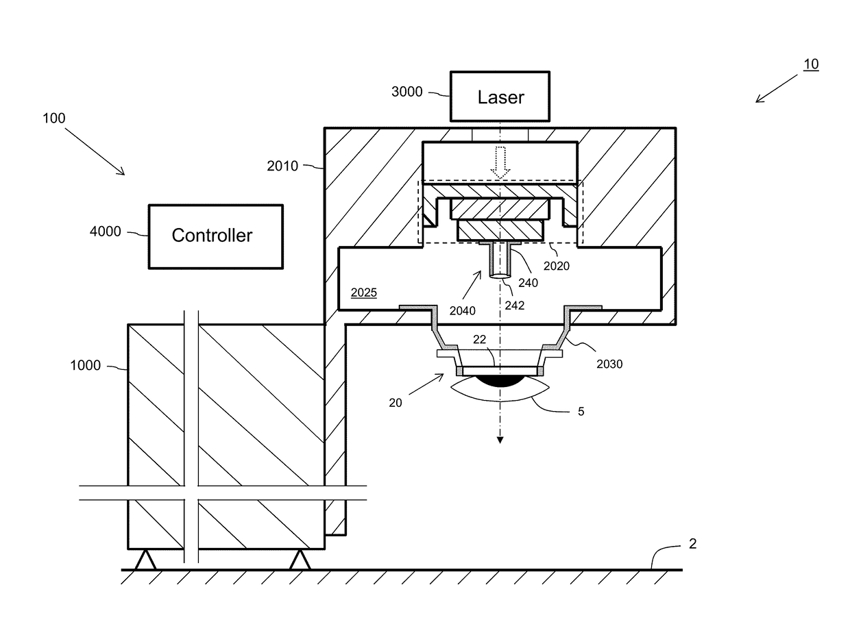
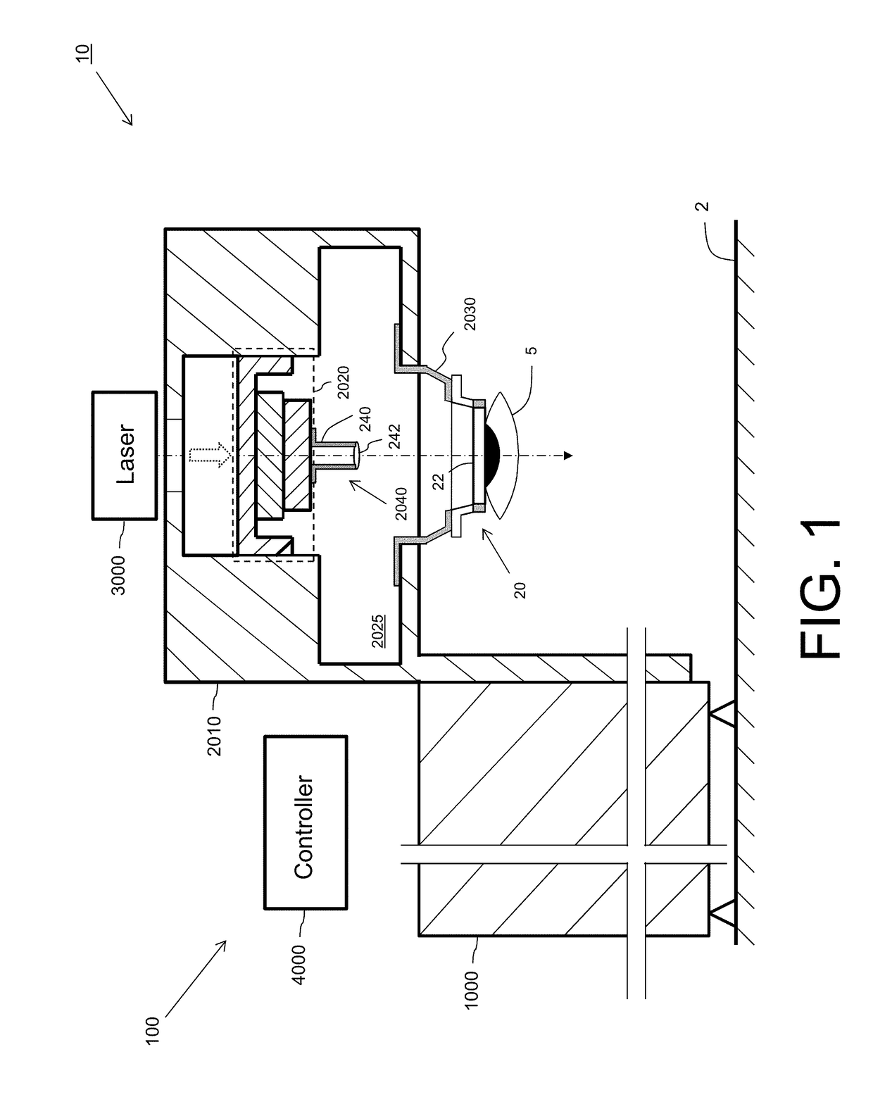
[0047]FIG. 1 illustrates an example embodiment of an arrangement 10 of a laser surgery apparatus 100 and an eye stabilization device.

[0048]Laser surgery apparatus 100 includes a structural frame or base 1000, a gantry 2010 movable in three dimensions and attached to the structural frame; an adjustable table 2020 attached to gantry 2010; a docking receptacle 2030; a lens assembly 2040 attached to adjustable table 2020; a laser 3000; and a controller 4000. Laser surgery apparatus 100 may include a numbe...


PUM


Abstract

A patient interface device includes: a first interface port configured to be interfaced with a laser surgery apparatus; a second interface port configured to be interfaced with a patient's eye, the second interface port including an applanating lens for application to a patient's eye during a laser surgery procedure; a chamber extending between the first interface port and the second interface port and defining a chamber therein, wherein air may be evacuated from the chamber by the laser surgery apparatus via the first interface port; and a tubular light guiding structure having at a first end thereof a light receiving surface, configured to receive light, and having at a second end thereof a light-emitting surface, wherein the second surface is disposed adjacent the applanating lens and configured to provide the light in a vicinity of the patient's eye when the applanating lens is applied to the patient's eye.

Description

RELATED APPLICATIONS[0001]This application claims priority to, and the benefit of, under 35 U.S.C. §119(e) of U.S. Provisional Appl. No. 62 / 318,693, filed Apr. 5, 2016, which is incorporated by reference herein in its entirety.TECHNICAL FIELD[0002]Embodiments of this invention pertain to laser eye surgery, and in particular to a patient interface device for docking a patient's eye to a laser surgery instrument during laser eye surgery, and more particularly such a patent interface device having a light guiding structure for illuminating the patient's eye.BACKGROUND AND SUMMARY[0003]Laser surgery has become an important technique for the treatment of vision problems. It is necessary to stabilize the patient's eye of a patient during laser surgery in a predetermined position relative to the focal point of the laser beam, by physically constraining eye movement with respect to the laser beam during such laser surgery.[0004]Toward this end, a patient interface device is typically applie...

Claims


Application Information

Patent Timeline
Patent Type & Authority Applications(United States)
IPC IPC(8): A61F9/009A61B3/14A61B18/22
CPCA61F9/009A61B2018/2272A61B3/14A61B18/22
Inventor GARCIA, JOSE L.ACCURSO, ROGER W.
Owner AMO DEVMENT
Why Eureka
Try Eureka