Check patentability & draft patents in minutes with Patsnap Eureka AI!

Overflow downdraw glass tube forming apparatus

Active Publication Date: 2017-10-05
CORNING INC
View PDF1 Cites 0 Cited by
  • Summary
  • Abstract
  • Description
  • Claims
  • Application Information

AI Technical Summary

Benefits of technology

This patent is about an apparatus for making glass tubing. It has a former with an outside and inside surface where molten glass flows to form fused glass tubing. The apparatus has multiple sources that supply the molten glass to flow on the outside and inside surfaces. In one embodiment, there are three layers of molten glass that meet at the bottom of the former to form a three-layer fused glass tubing. In another embodiment, there are more than two sources that supply the molten glass. The apparatus can produce a glass structure with several layers at the bottom of the former. The technical effect of this patent is to provide a method for making glass tubing with multiple layers of molten glass at the bottom of the former.

Problems solved by technology

During glass forming, when surfaces are touched by tooling, as is typical in current fabrication methods, the surface becomes damaged.
When viewed by the unaided eye, these damages are visible as optical distortions.
Damaged surfaces are undesirable for applications which require the highest optical quality, similar to that which is achieved with fusion-formed glass.
In addition, defects caused by tooling can decrease the strength and reliability of a tube.

Method used


Image

  • Overflow downdraw glass tube forming apparatus
  • Overflow downdraw glass tube forming apparatus
  • Overflow downdraw glass tube forming apparatus

Examples


Embodiment Construction

[0022]Reference will now be made in detail to embodiments of the present disclosure, examples of which are illustrated in the accompanying drawings. Whenever possible, the same reference numerals will be used throughout the drawings to refer to the same or like parts.

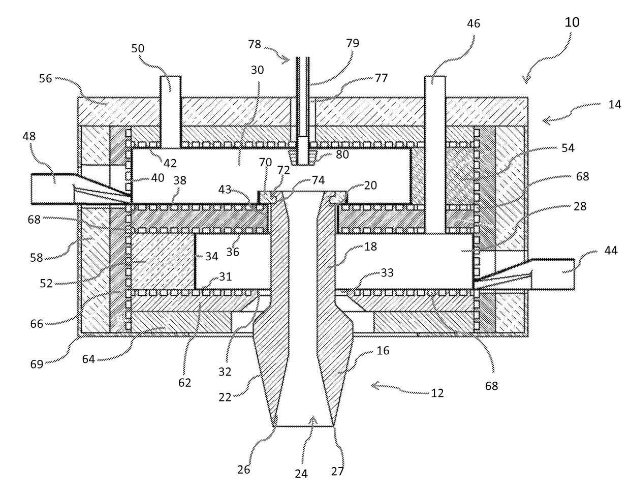
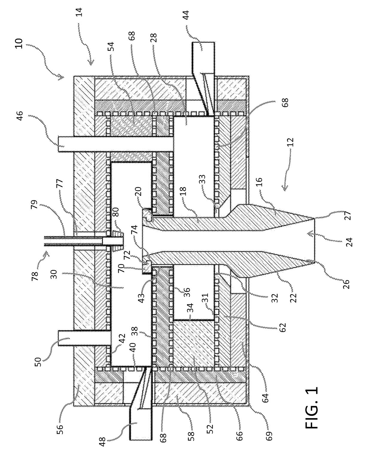
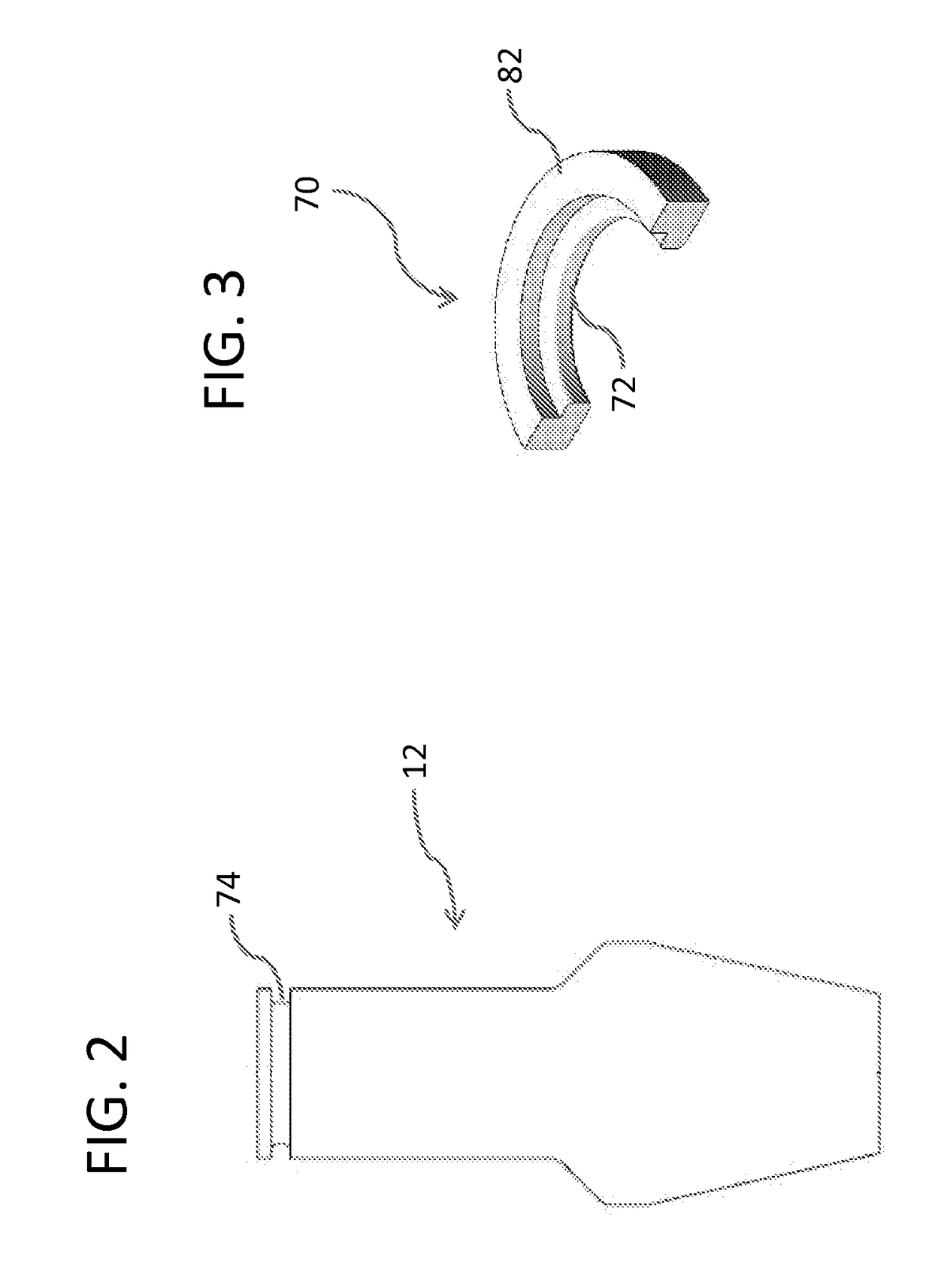
[0023]FIG. 1 is an elevated cross-sectional side view of one embodiment of a fused glass tube forming apparatus of the present disclosure. The apparatus for forming glass tubing 10 includes an endless former 12 and a molten glass hold 14. The endless former 12 is referred to as endless because it comprises a closed circuit, such as a circular ring, but may also be of a different shape, such as rectangular or square. As will be evident from the disclosure below, the shape of the endless former 12 generally defines the shape of the resulting fused glass tube made by the apparatus for forming glass tubing 10.

[0024]The endless former 12 has a lower portion 16, a middle portion 18 and an upper portion 20. The endless former ...


PUM

PropertyMeasurementUnit
Flow rateaaaaaaaaaa
Heightaaaaaaaaaa

Abstract

An apparatus for forming glass tubing is described. The apparatus for forming glass tubing comprises an endless former with an outer surface and an inner passage defining an inner surface. The apparatus for forming glass tubing further comprises two chambers from which molten glass may flow. One chamber flows molten glass to the outer surface of the endless former and another chamber flows molten glass to the inner surface of the endless former. The two flows of molten glass meet at the bottom of the former to form glass tubing.

Description

[0001]This application claims the benefit of priority under 35 U.S.C. §119 of U.S. Provisional Application Ser. No. 62 / 045,114, filed on Sep. 3, 2014, the content of which is relied upon and incorporated herein by reference in its entirety.BACKGROUND OF THE INVENTION[0002]The present disclosure relates generally to the manufacture of fused glass tubing, and, more particularly, to fused glass tubing formed from an overflow process.[0003]During glass forming, when surfaces are touched by tooling, as is typical in current fabrication methods, the surface becomes damaged. When viewed by the unaided eye, these damages are visible as optical distortions. Additionally, these defects are easily viewed as dark lines when observed via Xenon shadowgraph. Damaged surfaces are undesirable for applications which require the highest optical quality, similar to that which is achieved with fusion-formed glass. In addition, defects caused by tooling can decrease the strength and reliability of a tube...

Claims


Application Information

Patent Timeline
IPC IPC(8): C03B17/02C03B17/04
CPCC03B17/025C03B17/02C03B17/04
Inventor GALLAGHER, MICHAEL THOMASCIMO, PATRICK JOSEPHWHEELER, NICHOLAS RYANCOPPOLA, FRANKPETERSON, IRENE MONAPETERSON, RICHARD CURWOODBORATAV, OLUS NAILISHAY, GEORGE CLINTONALBEE, PAUL D.JOUBAUD, LAURENTBISSON, ANTOINE GASTONCOOK, GLEN BENNETT
Owner CORNING INC
Features
  • R&D
  • Intellectual Property
  • Life Sciences
  • Materials
  • Tech Scout
  • Unparalleled Data Quality
  • Higher Quality Content
  • 60% Fewer Hallucinations
Learn More