Shielded optical probe having an electrical connector

a technology of optical probes and electrical connectors, applied in the direction of coupling device connections, instruments, applications, etc., can solve the problems of sensor being rendered inoperable despite its useful life, sensor being limited to its useful life, wire or cable, etc., to prevent leakage of electromagnetic radiation, convenient to adapt to different monitoring equipment, and advantageous

Inactive Publication Date: 2006-11-07
JPMORGAN CHASE BANK NA
View PDF141 Cites 825 Cited by
  • Summary
  • Abstract
  • Description
  • Claims
  • Application Information

AI Technical Summary

Benefits of technology

[0012]In another aspect of the invention, an improved optical probe assembly is disclosed with an electrical connector designed to accept connections to various external monitoring equipment and may accept connections using various types of wires. Thus, the patient cable connector may be connected to, for example, a wireless transmitter and/or battery, eliminating the need for a wire at all. Additionally, the type of wire may be varied based on patient needs, and the replacement of wires and patient cable connectors may take place separately as needed from the replacement of optical probes.
[0013]In another aspect of the invention, an improved optical probe assembly is disclosed having an electrical connector adaptable for use with patient cable connectors designed for disposable, reusable, durable, and combination reusable/disposable sensors. Through the use of a standardized or universal patient cable connectors, optical sensors are advantageously used interchangeably and easily adapted to different monitorin...

Problems solved by technology

For example, the sensor is often limited to the useful life of the permanent plastic molded wire in that when the wire fails, the sensor is rendered inoperable despite its continuing functionality.
Likewise, when the sensor fa...

Method used


Image

  • Shielded optical probe having an electrical connector
  • Shielded optical probe having an electrical connector
  • Shielded optical probe having an electrical connector

Examples


Embodiment Construction

[0030]The invention is described in detail below with references to the figures, where like elements are referenced with like numerals throughout. The term probe and sensor are used interchangeably herein.

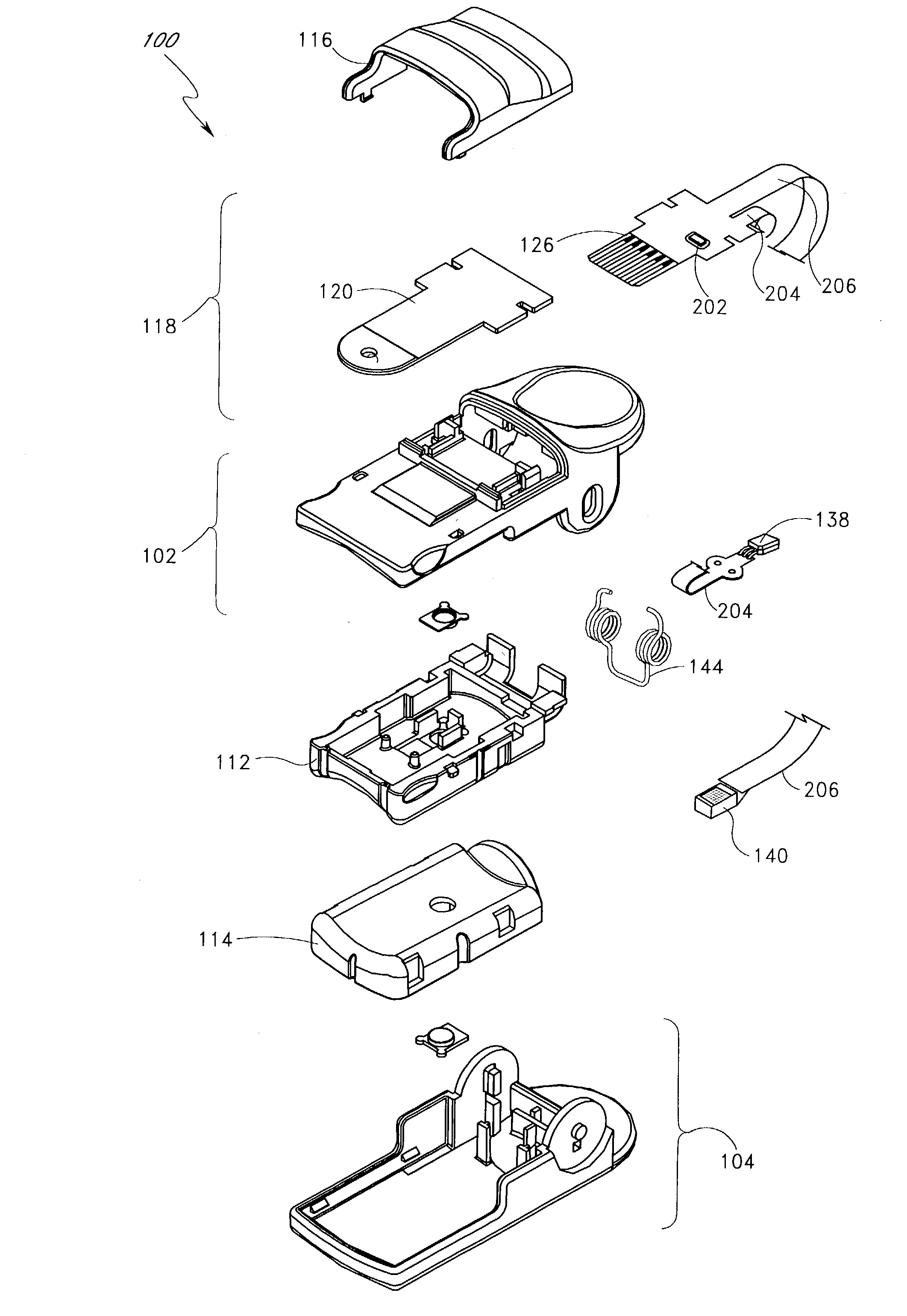
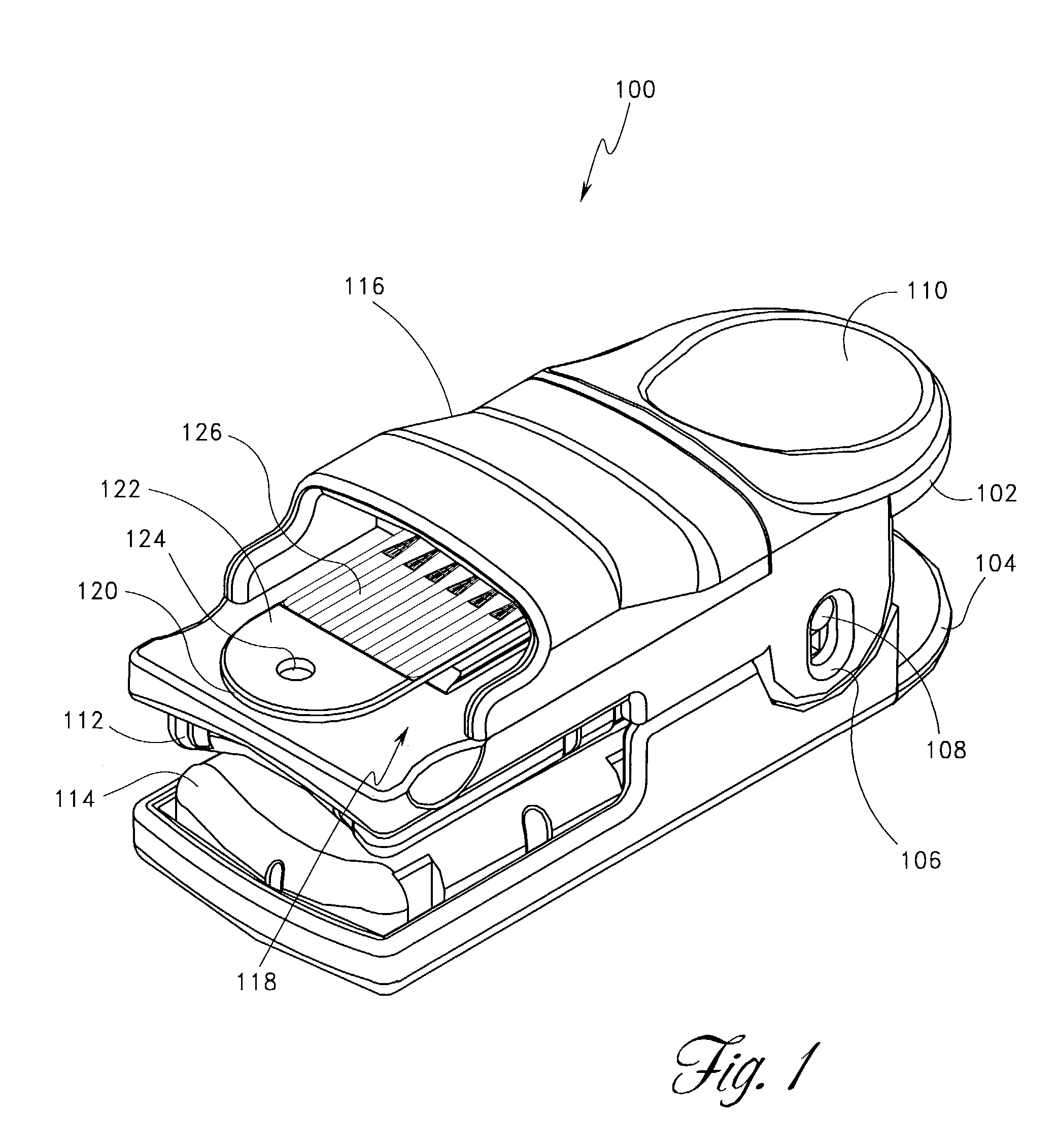
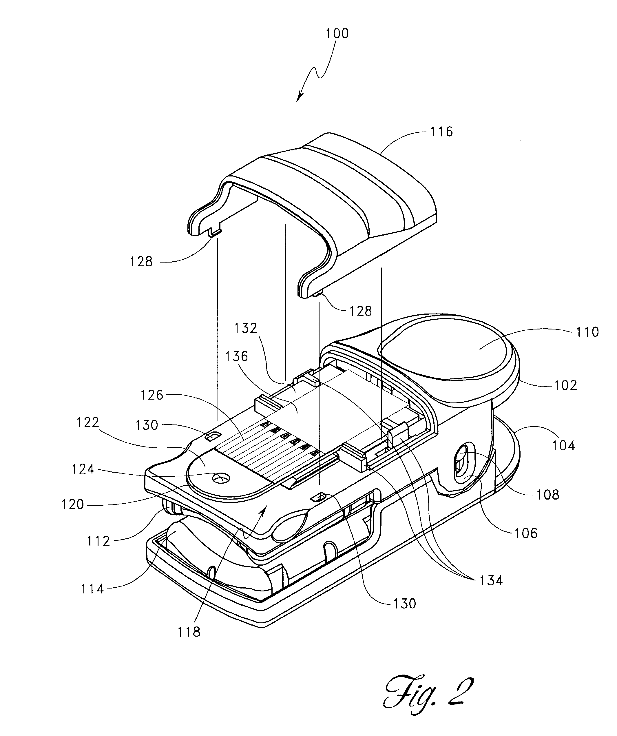
[0031]FIG. 1 illustrates an optical probe 100 according to one embodiment of the invention. As shown in FIG. 1, the optical probe 100 comprises an upper housing 102 and a lower housing 104. According to this embodiment, the upper housing 102 and the lower housing 104 oppose one another and are configured to include components designed to accept a measurement site for the tissue of a patient. For example, according to the embodiment shown in FIG. 1, the optical probe 100 is configured to accept a digit of a patient as a measurement site.

[0032]According to one embodiment, the upper and lower housings, 102 and 104, comprise injection moldable thermoplastic material or other suitable medium. As further illustrated in FIG. 1, the upper housing 102 comprises an aperture 106 while the low...


PUM


Abstract

A noninvasive optical probe has an electrical connector for connecting the optical probe to a cable connector. According to one embodiment, the electrical connector includes a durable flexible tab suspended between the housing of the optical probe and a protective cover. The electrical connector also advantageously forms, according to various embodiments, a flexible, plugable, lockable, removable, and sealable electrical connection.

Description

REFERENCE TO RELATED APPLICATIONS[0001]The present application claims priority under 35 U.S.C. § 122 to the following patent applications, all of which are incorporated herein by reference. The present application is a continuation of U.S. patent application Ser. No. 09 / 770,757, filed Jan. 25, 2001 now U.S. Pat. No. 6,541,756, entitled “SHIELDED OPTICAL PROBE HAVING AN ELECTRICAL CONNECTOR,” which is a continuation-in-part of U.S. patent application Ser. No. 09 / 420,544, filed Oct. 19, 1999 now U.S. Pat. No. 6,580,086, entitled “SHIELDED OPTICAL PROBE AND METHOD.” The present application is also continuation-in-part of U.S. patent application Ser. No. 09 / 094,202, filed Jun. 9, 1998, entitled “LOW-NOISE OPTICAL PROBES,” now U.S. Pat. No. 6,256,523, which is a continuation of U.S. patent application Ser. No. 08 / 543,789, filed Oct. 16, 1995, entitled “LOW-NOISE OPTICAL PROBES,” now U.S. Pat. No. 5,782,757, which is a continuation-in-part of U.S. patent application Ser. No. 08 / 333,132, f...

Claims


Application Information

Patent Timeline
IPC IPC(8): H01J40/14A61B5/00A61B5/024G01N21/86H01R13/26H01R13/627H05K1/18
CPCA61B5/02427A61B5/14552A61B5/6826A61B5/6829A61B5/6838H01R13/26H01R13/6275H01R23/10A61B2562/08H01R2201/12H05K1/189H01R12/62H01R24/00
Inventor SCHULZ, CHRISTIAN E.AL-ALI, AMMARMASON, EUGENE E.MILLS, MIKE A.
Owner JPMORGAN CHASE BANK NA
Why Eureka
Try Eureka