Systems and methods for automatically cleaning a lavatory floor

a technology of automatic cleaning and lavatory floor, which is applied in the direction of cleaning equipment, cleaning using liquids, transportation and packaging, etc., can solve the problems of increased likelihood of germs and bacteria in the lavatory onboard the aircraft, and affecting the cleanliness of the lavatory. , to achieve the effect of effective and efficient cleaning of the lavatory floor onboard

Active Publication Date: 2017-10-05
THE BOEING CO
View PDF2 Cites 17 Cited by
  • Summary
  • Abstract
  • Description
  • Claims
  • Application Information

AI Technical Summary

Benefits of technology

[0008]A need exists for a system and a method for cleaning a floor. A need exists for a system and method for automatically cleaning a floor of a lavatory after use. A need exists for a system and a method for effectively and efficiently cleaning a lavatory floor onboard an aircraft, particularly during a flight.

Problems solved by technology

As can be appreciated, with each use, the cleanliness of a lavatory onboard an aircraft may be compromised.
Individuals onboard may be sensitive to health risks presented by a frequently-used lavatory onboard an aircraft.
Indeed, as each individual uses a lavatory onboard an aircraft, the likelihood of germs and bacteria therein increases.
However, during a flight, the lavatory is typically not cleaned, despite the fact that numerous individuals may use the lavatory during the flight.
While flight attendants may be able to clean the lavatory, they are usually preoccupied with other duties during the flight.
As such, cleaning the lavatory may not be a top priority for flight attendants during a flight or even between flights.
Consequently, the cleanliness of lavatories onboard an aircraft may be compromised, particularly during flights.
In general, during a flight, a lavatory onboard an aircraft may become dirty, wet, smelly, and the like due to use by individuals onboard the aircraft during the flight.
As such, a flight experience for individuals onboard the aircraft may be negatively impacted.
Even after being cleaned, the floor of the lavatory may be wet from cleaning fluids.
A wet lavatory floor may be unsettling to individuals, even if they know the floor is clean.
That is, a wet floor may give the impression of unsanitary conditions.
Further, a wet floor may pose a safety hazard in that an individual may slip and fall on the wet floor.

Method used


Image

  • Systems and methods for automatically cleaning a lavatory floor
  • Systems and methods for automatically cleaning a lavatory floor
  • Systems and methods for automatically cleaning a lavatory floor

Examples


Embodiment Construction

[0029]The foregoing summary, as well as the following detailed description of certain embodiments will be better understood when read in conjunction with the appended drawings. As used herein, an element or step recited in the singular and preceded by the word “a” or “an” should be understood as not necessarily excluding the plural of the elements or steps. Further, references to “one embodiment” are not intended to be interpreted as excluding the existence of additional embodiments that also incorporate the recited features. Moreover, unless explicitly stated to the contrary, embodiments “comprising” or “having” an element or a plurality of elements having a particular condition may include additional elements not having that condition.

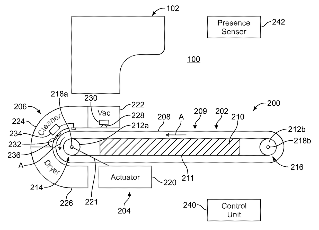
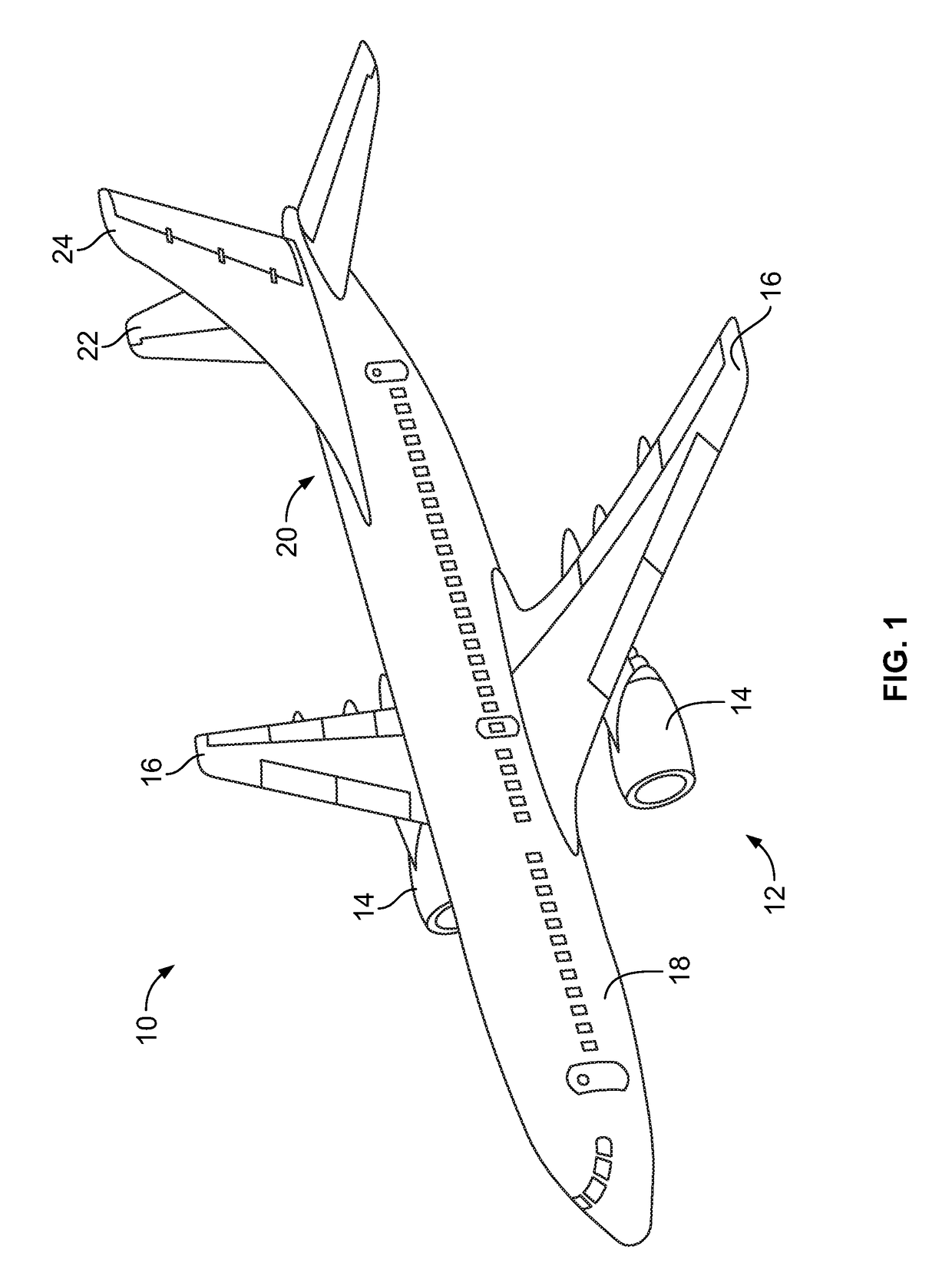
[0030]Embodiments of the present disclosure provide a self-cleaning floor assembly that may be used in a lavatory, such as a lavatory within a commercial aircraft. The self-cleaning floor assembly includes a moveable floor that is operatively coupled...


PUM


Abstract

A self-cleaning floor assembly is configured to form or be positioned on a floor of an enclosed space. The self-cleaning floor assembly includes a moveable floor including a moveable floor panel, an actuation system that is operatively coupled to the floor panel, and a cleaning system proximate to at least a portion of the moveable floor. The actuation system is configured to move at least a portion of the floor panel into and through the cleaning system during a cleaning cycle. The cleaning system is configured to clean the portion(s) of the floor panel during the cleaning cycle.

Description

RELATED APPLICATIONS[0001]This application relates to and claims priority benefits from U.S. Provisional Patent Application No. 62 / 316,012, entitled “Systems and Methods for Automatically Cleaning a Lavatory Floor,” filed Mar. 31, 2016, which is hereby incorporated by reference in its entirety.FIELD OF THE DISCLOSURE[0002]Embodiments of the present disclosure generally relate to systems and methods for automatically cleaning a floor, such as a lavatory floor within a commercial aircraft.BACKGROUND OF THE DISCLOSURE[0003]Commercial aircraft are used to transport passengers between various locations. During a flight—particularly a trans-oceanic or other long haul flight—passengers are typically confined within certain areas (for example, cabins) of an aircraft. Various individuals (such as passengers, pilots, flight attendants, and the like) use certain internal portions of an aircraft during a flight. For example, numerous individuals may use a lavatory within an internal cabin durin...

Claims


Application Information

Patent Timeline
Patent Type & Authority Applications(United States)
IPC IPC(8): E03D9/00A47L9/14B08B1/00B64D11/02B08B3/04B08B3/08B08B7/00B64F5/00A47L7/00B08B1/02
CPCE03D9/002A47L7/0004A47L9/1409B08B1/006B64D11/02B08B3/041B08B3/08B08B7/0057B64F5/0018B08B1/02E03D9/00B08B5/04B64C1/18B64F5/00B64F5/30
Inventor JENSEN, CHARLES C.
Owner THE BOEING CO
Why Eureka
Try Eureka