Turbidimeter with ultrasonically cleaned components

a technology of components and turbidimeters, applied in the direction of cleaning processes, instruments, cleaning liquids, etc., can solve the problems of user inconvenience, time-consuming and inefficient, and inability to accurately detect the turbidimeter, so as to reduce the tedium and service interruptions, the effect of reducing the inefficiency and reducing the inefficiency

Active Publication Date: 2009-01-08
HF SCI INC
View PDF11 Cites 8 Cited by
  • Summary
  • Abstract
  • Description
  • Claims
  • Application Information

AI Technical Summary

Benefits of technology

[0008]It is therefore an object of the present disclosure to provide an apparatus for automatically and continuously cleaning and deterring particulate build-up on the glassware that accommodates a test sample in a turbidimeter or other optical water-testing instrument. It is a further object of this disclosure to provide an ultrasonic optical cleaning system that significantly reduces the inefficiency, tedium and service interruptions associated with manual cleaning. It is a further object of this disclosure to provide an apparatus for ultrasonically cleaning turbidimeter glassware, which apparatus is not hard-wired to the electronics of the turbidimeter so that the glassware can be conveniently indexed and / or removed for recalibration, as needed.
[0009]It is a further object of this disclosure to provide an apparatus that effectively and efficiently cleans the glassware used in a water-testing instrument so that improved, accurate water quality measurements are obtained.
[0010]It is a further object of this disclosure to provide an apparatus for ultrasonically cleaning a turbidimeter cuvette, which apparatus cleans and deters the buildup of both inorganic and organic contaminates so that the user does not have to manually clean the glassware and recalibration of the turbidimeter is significantly reduced.
[0011]This disclosure features an ultrasonic optical cleaning system for use with glassware of the type used in optical water testing equipment. The system includes an ultrasonic transducer that is secured to the glassware to be cleaned. The transducer includes a material that vibrates when a selected voltage is applied to the transducer. The transducer is electrically connected to an ultrasonic control circuit by means of a contact connector cap. The ultrasonic control circuit delivers an electrical signal through the connector cap to the transducer so that the transducer vibrates to clean particulate matter from the glassware and prevent the build-up of particulates on the surface of the glassware.
[0013]The ultrasonic control circuit may comprise an ultrasonic printed circuit board that is operably mounted to the printed circuit board that controls operation of the water testing equipment. The ultrasonic control circuit may receive power from the principal operating circuit of the test equipment. The control circuit typically delivers a voltage through the connector cap to the transducer and sweeps through a series of frequencies over a predetermined time span. Typically, the frequencies include the resonant frequency for the transducer-cuvette assembly such that the transducer exhibits a maximum vibration and energy is transferred to the glassware at a sufficient level so that optimum cleaning is achieved. Because the glassware is maintained substantially free of organic and inorganic particulates, improved measurements of water quality are obtained. At the same time, maintenance requirements are reduced considerably.

Problems solved by technology

Over time, inorganic particulates and organic contaminates such as algae tend to build up on the surface of the glassware holding the test sample.
If the cuvette is not cleaned, the dirt can distort the measurements taken by the turbidimeter, which can produce erroneous readings.
This tends to be tedious, time consuming and inefficient.
The user is likely to experience undesirable “down-time” as turbidity readings cannot be taken while the instrument is being serviced.

Method used


Image

  • Turbidimeter with ultrasonically cleaned components
  • Turbidimeter with ultrasonically cleaned components
  • Turbidimeter with ultrasonically cleaned components

Examples


Embodiment Construction

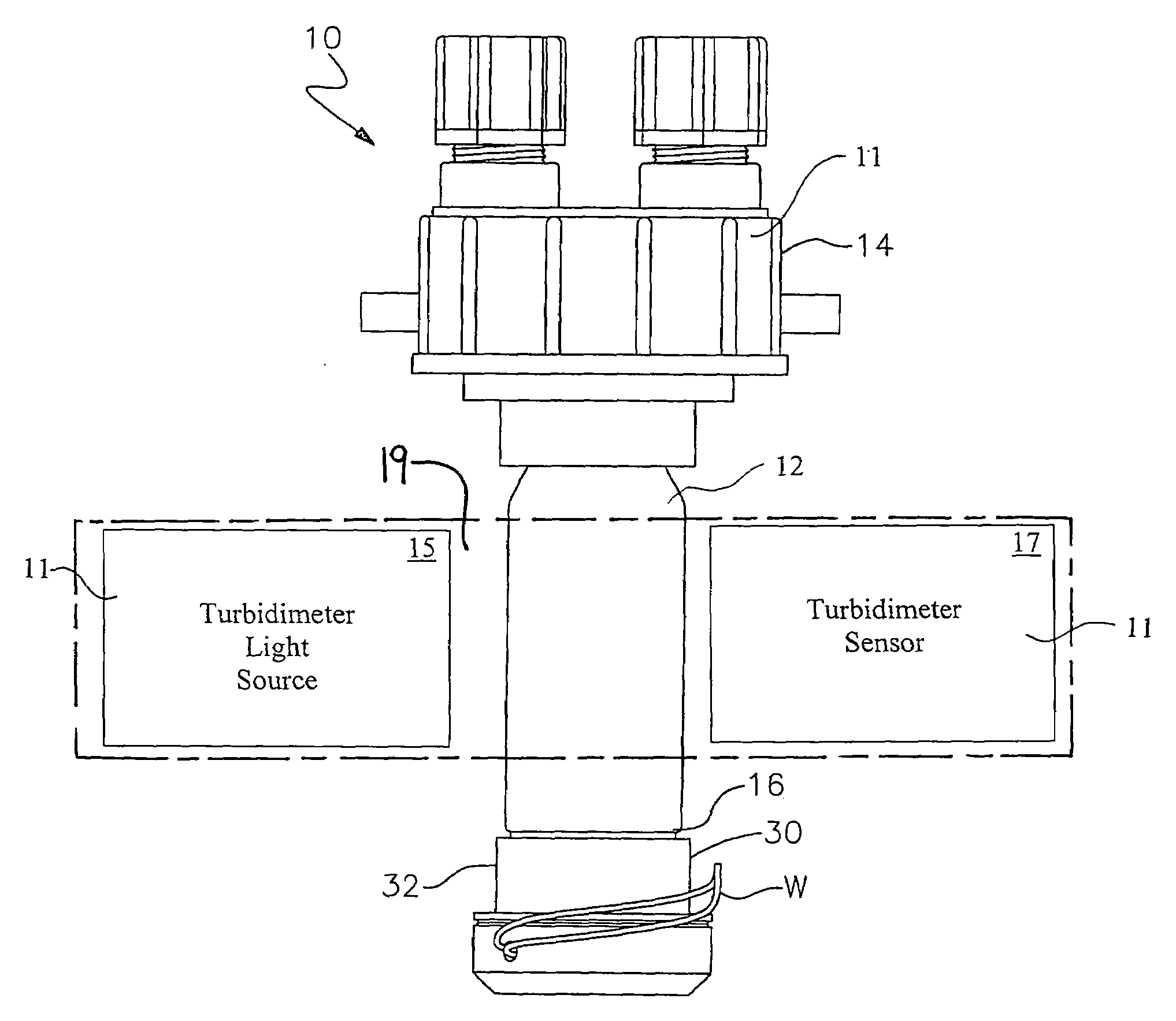
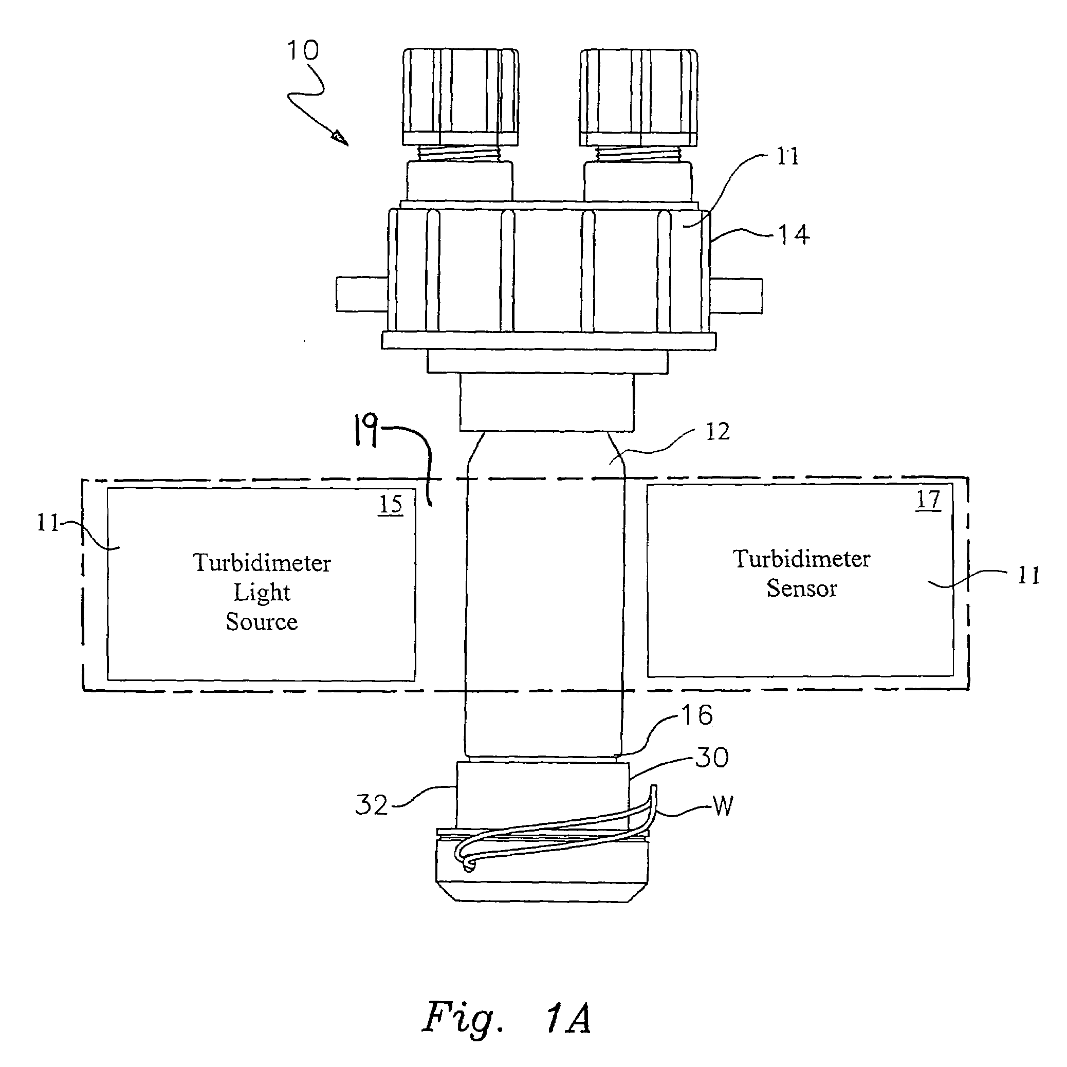
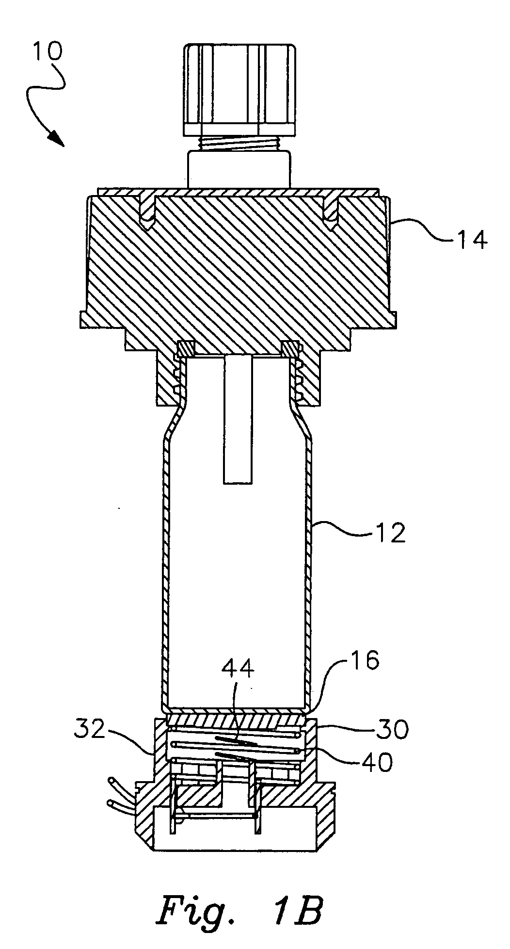
[0026]The present disclosure overcomes many of the prior art problems associated with optical measurement systems that require periodic cleaning. The advantages, and other features of the systems and methods disclosed herein, will become more readily apparent to those having ordinary skill in the art from the following detailed description of certain preferred embodiments taken in conjunction with the drawings which set forth representative embodiments of the present invention and wherein like reference numerals identify similar structural elements. Additionally, for clarity items have not been included in the Figures or have been represented somewhat schematically as would be appreciated by those of ordinary skill in the pertinent art. Unless otherwise specified, the illustrated embodiments can be understood as providing exemplary features of varying detail of certain embodiments, and therefore, unless otherwise specified, features, components, modules, elements, and / or aspects of ...


PUM

PropertyMeasurementUnit
voltageaaaaaaaaaa
voltageaaaaaaaaaa
optical measurementaaaaaaaaaa

Abstract

An ultrasonic optical cleaning system is provided for cleaning and deterring the buildup of organic and inorganic particulates from the surface of glassware used in water testing instrumentation. The ultrasonic optical cleaning system includes a transducer that is attached to the surface of the glassware. A connector cap carrying a plurality of spring contacts interconnecting the transducer with an ultrasonic transducer control circuit. The control circuit operates continuously to provide an electrical signal to the transducer that vibrates the transducer and the glassware so that the glassware is cleaned of contaminates.

Description

CROSS-REFERENCE TO RELATED APPLICATIONS[0001]This application claims the benefit of U.S. Provisional Patent Application Ser. No. 60 / 513,857 filed Oct. 24, 2003 and U.S. Utility patent application Ser. No. 10 / 972,849 filed Oct. 25, 2004, each of which is incorporated by reference in its entirety.FIELD OF THE INVENTION[0002]This invention relates to a system that ultrasonically cleans and deters the buildup of particulate matter on glassware of the type used in optical water testing equipment. The apparatus is particularly suited for use in cleaning a tube or cuvette that supports a water sample in a turbidimeter.BACKGROUND OF THE INVENTION[0003]Turbidimeters are widely utilized to test public water supplies for the presence of particulate matter suspended in the water. Examples of these instruments include the turbidimeter disclosed in U.S. Pat. No. 5,446,544 (the '544 patent), as well as the updated version distributed by HF Scientific, Inc. under the brand name MICRO TOL™. These an...

Claims


Application Information

Patent Timeline
Patent Type & Authority Applications(United States)
IPC IPC(8): G01N21/59B08B13/00
CPCB08B3/12B08B9/08G01N2021/154B08B2209/005G01N21/15B08B9/22
Inventor CONNELLY, ROWANCONDON, PAULLEAL, JOEL
Owner HF SCI INC
Why Eureka
Try Eureka