Precision vacuum cleaner head

a vacuum cleaner and vacuum head technology, applied in the field of precision vacuum cleaners, can solve the problems of ineffective full cleaning, handheld vacuum units, lack of capacity to clean these areas, etc., and achieve the effect of efficient brushing and vacuuming soiled surfaces, compact design, and effective cleaning of flat and cornered soiled surfaces

Inactive Publication Date: 2006-11-09
SMITH RICHARD A
View PDF6 Cites 6 Cited by
  • Summary
  • Abstract
  • Description
  • Claims
  • Application Information

AI Technical Summary

Benefits of technology

[0005] It is an object of the present invention to provide a precision vacuum cleaner head which can be used on normal vacuum cleaners and also advantageously employed for portable, handheld vacuuming units.
[0006] It is a further object of the present invention to provide a precision vacuum cleaner head which is compact in design, but effectively cleans flat and cornered soiled surfaces.
[0007] It is another object of the present invention to provide a precision vacuum cleaner head which employs two different sized rotary brush members to efficiently brush and vacuum soiled surfaces.
[0008] It is still another object of the present invention to provide a precision vacuum cleaner head which has a tapered housing configuration and which, in tandem with dual rotating brush members, effectively and efficiently cleans flat surfaces and corners.

Problems solved by technology

While such vacuum cleaner heads have been designed and manufactured with a variety of shapes and designs, there have been no heads which efficiently and effectively clean both soiled flat surfaces and corners and below edges or cantilevered areas.
Handheld vacuum units, especially, lack the capacity to clean these areas.
For example, handheld units used to clean pool table surfaces do not have access to areas under the table's cantilevered side rails, and so are ineffective in providing full cleaning.
Such a configuration is also not efficient in adequately cleaning flat surfaces and corners.

Method used


Image

  • Precision vacuum cleaner head
  • Precision vacuum cleaner head
  • Precision vacuum cleaner head

Examples


Embodiment Construction

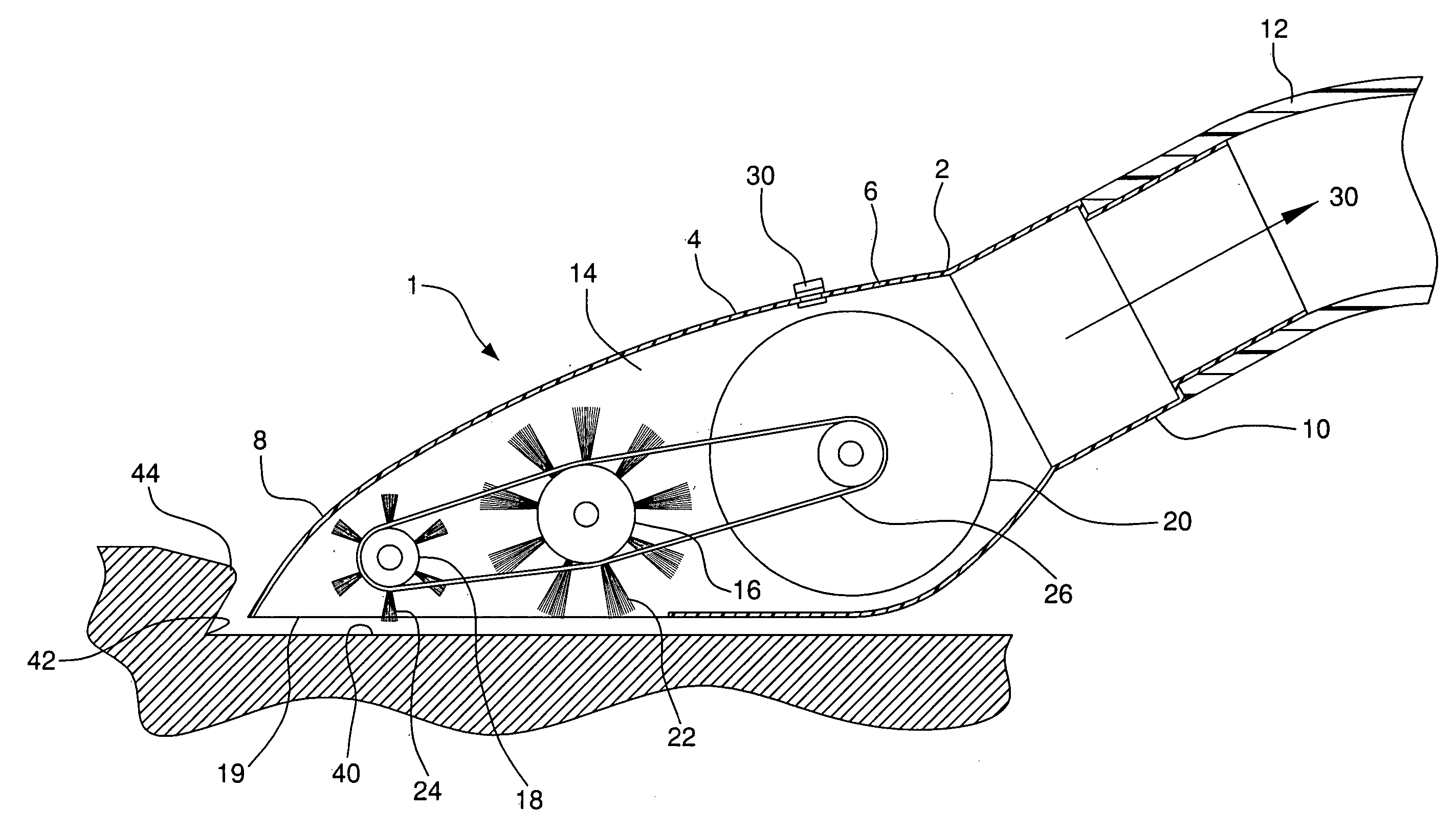
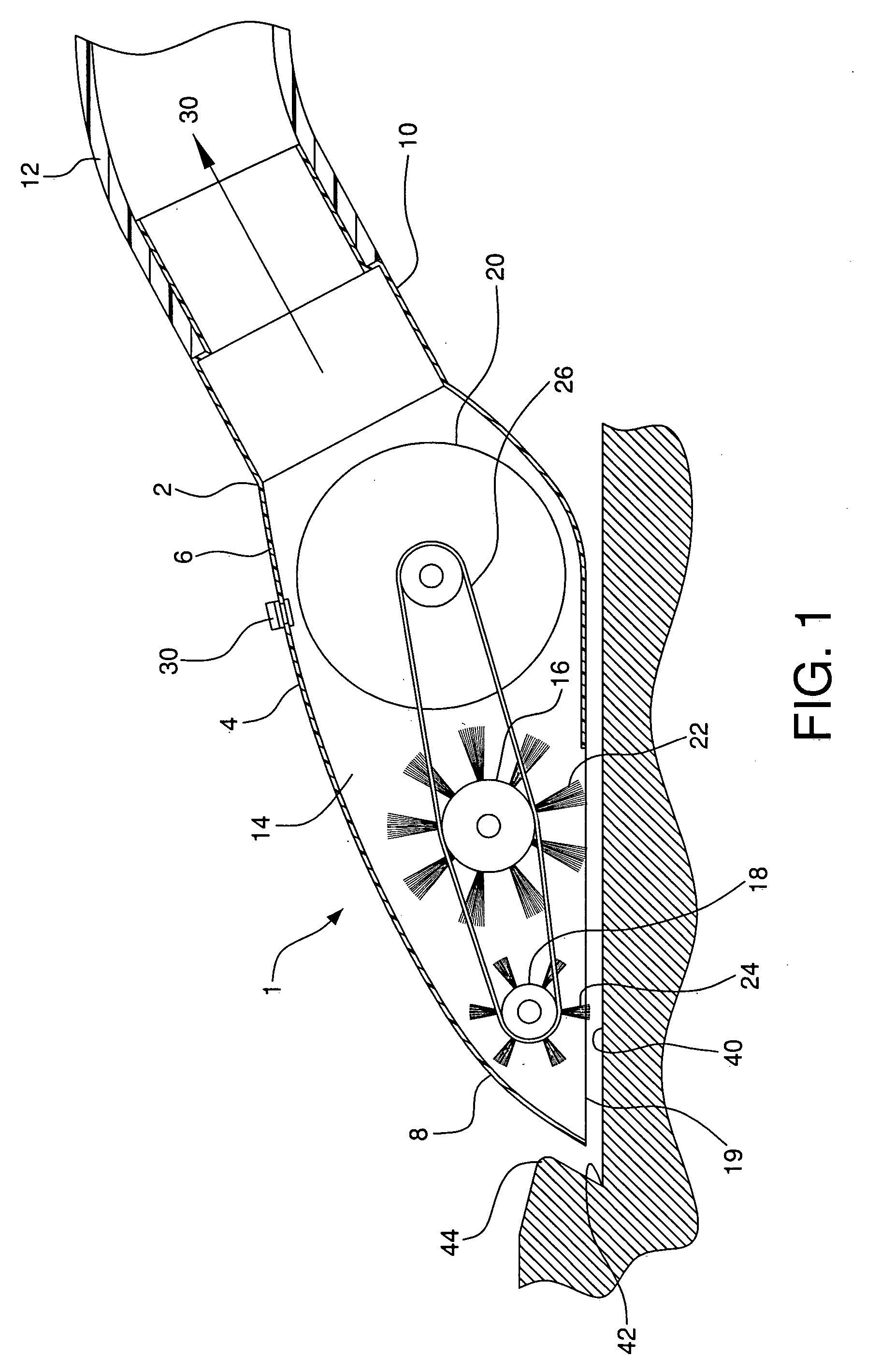
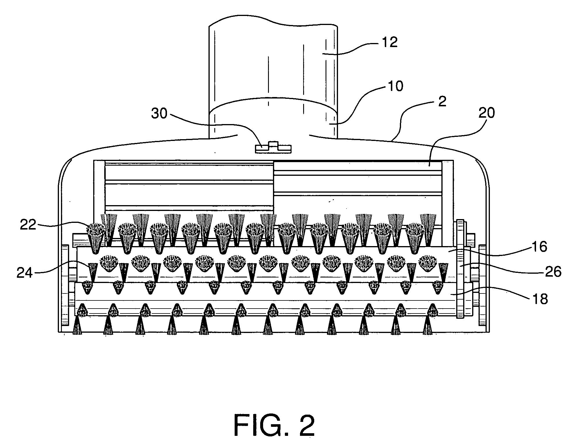
[0014] Precision vacuum cleaner head 1 of the present invention is configured to be used with a variety of vacuum cleaning units, and is especially adaptable for use with portable handheld cleaner units. Cleaner head 1 comprises housing 2 whose upper surface 4 is tapered gradually downward, from after section 6 to forward tapered section 8 of the housing. Housing 2 has extension section 10 which is configured for attachment to section connection line 12 which heads to the vacuum source of the cleaning unit.

[0015] Enclosed within housing 2 is substantially open chamber 14. Located within chamber 14 is first cylindrical rotary brush member 16, second cylindrical rotary brush member 18, and turbo drive wheel 20. First brush member 16 is larger in diameter than second brush member 18. First brush member 16 also has longer bristles 22 than second brush member 18, whose bristles 24 may also be finer than bristles 22. Suction opening 19 at the bottom of housing 2 allows bristles 22 and 24...


PUM


Abstract

A precision vacuum cleaner head is to be employed on a variety of vacuum cleaning units, the head being especially adaptable for use with portable, handheld vacuum cleaning units. The head has a tapered outer housing configured to enter and clean corners. The housing encloses a chamber which has two different sized rotary brush members, the smaller of which is located at the tapered end of the housing. Airflow suction from the vacuum cleaner provides a vacuum suction airflow in the housing. This airflow acts on a turbo drive wheel to rotate both brush members. The tapered housing permits efficient and effective cleaning of both flat surfaces and corners.

Description

BACKGROUND OF THE INVENTION [0001] Vacuum cleaner heads commonly comprise an outer housing with an extended section attached to a suction connection line which receives suctioned airflow generated by a vacuum cleaning unit. A suction opening is normally located at the lower part of the housing and a rotary brush member is mounted in the housing and is located close to this suction opening. The rotary brush member is routinely driven by a turbine drive wheel which is caused to turn when acted upon by the flow of the suction air from the vacuum cleaning unit. The drive wheel turns the rotary brush member. Bristles on the rotary brush member extend out through the housing's suction opening and the rotation of the brush member and its bristles in combination with the vacuum suction, brushes up and suctions dirt from soiled surfaces below the opening. [0002] While such vacuum cleaner heads have been designed and manufactured with a variety of shapes and designs, there have been no heads ...

Claims


Application Information

Patent Timeline
Patent Type & Authority Applications(United States)
IPC IPC(8): A47L9/06
CPCA47L9/0488A47L9/0416
Inventor SMITH, RICHARD A.
Owner SMITH RICHARD A
Why Eureka
Try Eureka