Optical Fiber, and Optical-Fiber Production Method

a production method and optical fiber technology, applied in the field of optical fibers, can solve the problems of increasing the difficulty of connecting single-core fibers, and approaching the limit of the transmission capacity of presently used single-core optical fibers, and achieve the effect of easy identification

Active Publication Date: 2017-10-05
FURUKAWA ELECTRIC CO LTD
View PDF0 Cites 1 Cited by
  • Summary
  • Abstract
  • Description
  • Claims
  • Application Information

AI Technical Summary

Benefits of technology

[0032]The present embodiments can provide an optical fiber of which the core arrangement can be easily identified from an outer surface of a resin coating thereof, and the like.

Problems solved by technology

Due to rapidly increasing traffic in optical communications in recent years, the transmission capacity of presently used single-core optical fibers is approaching its limit.
On the other hand, a multi-core fiber has cores arranged at positions other than the center of the cross section, and this leads to a problem that the connection thereof is more difficult compared to connection of single-core fibers.
Moreover, besides multi-core fibers, when compared with connections of commonly used single-core optical fibers, it is still difficult as in the case of multi-core fibers to connect optical fibers in which a form of a cross section of the optical fiber taken in a perpendicular direction to a longitudinal direction thereof has an orientation in a rotational direction with the longitudinal direction of the optical fiber as an axis (such as eccentric core fibers or polarization-maintaining fibers).
However, with the method disclosed in JP A 2011-170099 in which a marker with different refractive index is provided inside the cladding cross section, it is impossible to identify the core arrangement unless the cross section is cut or a resin coating of side surface of the cladding is removed and the position of the marker is observed under a microscope.
Thus, it is difficult to easily identify the core arrangement from appearance.

Method used


Image

  • Optical Fiber, and Optical-Fiber Production Method
  • Optical Fiber, and Optical-Fiber Production Method
  • Optical Fiber, and Optical-Fiber Production Method

Examples


first embodiment

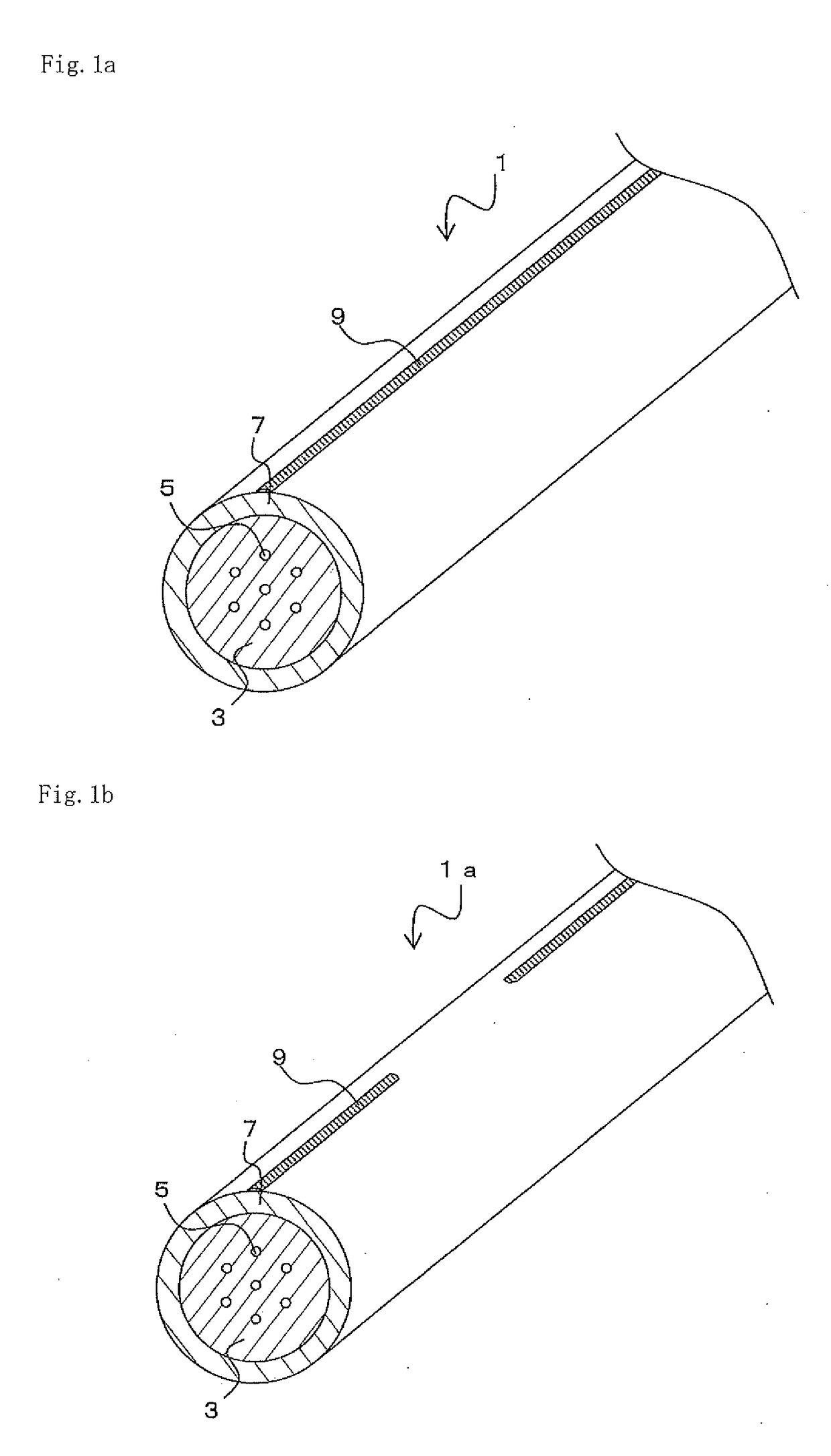
[0054]Hereinafter, an optical fiber according to an embodiment will be described. FIG. 1a is a schematic view of a multi-core fiber 1, which is an optical fiber.

[0055]The multi-core fiber 1 is an optical fiber that has a circular cross section, and includes a plurality of cores 5, which are arranged at predetermined intervals, and a cladding 3, which has a refractive index lower than that of a plurality of the cores and are formed on the periphery of a plurality of the cores. For example, the multi-core fiber 1 has total of the seven cores 5, one of which is disposed at the center of the multi-core fiber 1 with the others surrounding the center core and being disposed at each vertices of a regular hexagon. That is, the center core 5 and the other surrounding six cores 5 are all at regular intervals. Also, for the six cores 5, the distance between the adjacent cores 5 is the same. The core 5 becomes a waveguide for signal light. The arrangement of the cores 5 is not limited to the ex...

second embodiment

[0100]Next, a second embodiment will be described. In the first embodiment, an example in which the light introducing part 13 is at an end of the multi-core fiber 1 was described. With this method, light can be introduced into a selected particular core only. However, another method can be used to introduce light into the multi-core fiber 1.

[0101]FIG. 8a is a drawing showing a colored resin applying apparatus 10a. In the descriptions hereinafter, the same notations will be used for the same compositions as in the colored resin applying apparatus 10 and redundant descriptions will be omitted. The colored resin applying apparatus 10a is approximately similar to the colored resin applying apparatus 10 except for a light introducing part 13a, which substitutes the light introducing part 13.

[0102]The light introducing part 13a includes a light-introducing bending portion 27 and a light source between a pair of guides 29. The light-introducing bending portion 27 is a roller that bends the...

third embodiment

[0105]Next, a third embodiment will be described. FIG. 8b is a drawing showing a colored resin applying apparatus 10b. The colored resin applying apparatus 10b is approximately similar to the colored resin applying apparatus 10 except that the bobbin controller 25 controls the bobbin 22, not the bobbin 12.

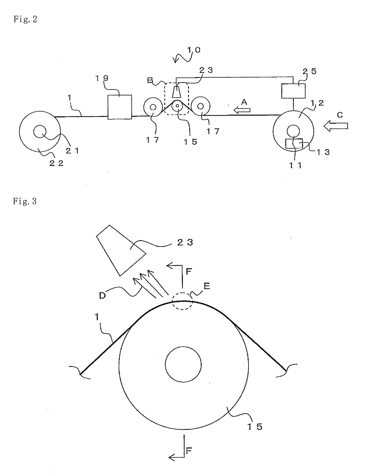
[0106]In the colored resin applying apparatus 10b, like in the colored resin applying apparatus 10, the optical detector 23 detects intensity of light leaked from the optical fiber bending part 15 and the twisting of the multi-core fiber 1 in the rotational direction is detected. The bobbin controller 25 controls the posture of the bobbin 22 corresponding to the rotational direction and the rotation amount of the multi-core fiber 1 found out from the intensity of leaked light detected. More specifically, the bobbin controller 25 tilts a rotational surface of the bobbin 22. Thus, it is possible to always maintain the uniform positions of the cores 5 on the cross section perpendicula...


PUM


Abstract

In this multi-core fiber, a plurality of cores are arranged at a prescribed interval, and the peripheries thereof are covered by a cladding having a lower refractive index than the plurality of cores. A resin coating is formed on the outer periphery of the cladding. A colored section is formed on a section of the outer surface of the resin coating in the peripheral direction. The colored section is formed continuously along the length direction of the multi-core fiber. In a multi-core fiber cross section orthogonal to the length direction, the position of a specific core and the peripheral position where the colored section is formed are substantially constant along the length direction of the multi-core fiber. In other words, in the multi-core fiber cross section orthogonal to the length direction, the position of the specific core and the position where the colored section is formed are substantially constant along the length direction of the multi-core fiber.

Description

TECHNICAL FIELD[0001]This disclosure relates to an optical fiber and the like.BACKGROUND[0002]Due to rapidly increasing traffic in optical communications in recent years, the transmission capacity of presently used single-core optical fibers is approaching its limit. So, as a means to further expand the communication capacity, multicore fibers in which a plurality of cores are formed in one fiber have been proposed. Use of multi-core fibers can suppress the laying cost of optical fibers and expand the transmission capacity.[0003]When a multi-core fiber is used as a transmission path, each of the core parts of the multicore fiber needs to be connected to another multi-core fiber, an optical element, or the like respectively to send and / or receive transmission signals.[0004]On the other hand, a multi-core fiber has cores arranged at positions other than the center of the cross section, and this leads to a problem that the connection thereof is more difficult compared to connection of ...

Claims


Application Information

Patent Timeline
Patent Type & Authority Applications(United States)
IPC IPC(8): G02B6/02G02B6/44G02B6/024
CPCG02B6/02042G02B6/024G02B6/4482G02B6/448G02B6/4404G02B6/02395
Inventor KOKURA, KUNIO
Owner FURUKAWA ELECTRIC CO LTD
Why Eureka
Try Eureka