
Turboengine, and vane carrier unit for turboengine

Active Publication Date: 2017-10-12
ANSALDO ENERGIA SWITZERLAND AG
View PDF4 Cites 1 Cited by
  • Summary
  • Abstract
  • Description
  • Claims
  • Application Information

AI Technical Summary

Benefits of technology

[0047]FIG. 3 shows detail A of FIGS. 1 and 2, setting forth in more detail a support arrangement through which guide vane member 20 is supported by outer wall structure 11. Guide vane member 20 comprises one or more airfoils 21 and an outer platform 22, which constitutes a radially outer end of guide vane member 20. The support arrangement comprises a radially and axially fixed support assembly 15, provided at an upstream end of guide vane member 20, and an auxiliary support assembly 16, provided at a downstream end of guide vane member 20. Male support elements 25 and 26 extend radially outwardly from outer platform 22 and are received in female support features of outer wall structure 11. FIG. 4 shows more details of radially and axially fixed support assembly 15. Male support element 25 comprises a lug 251 which in turn comprises a locking protrusion 252. Lug 251 is received in a slot of the outer wall structure. The slot is provided with an undercut, which in turn receives locking protrusion 252. Lug 251 is received in the slot in a snug fit, that is, at least essentially without play, in the axial direction. Locking protrusion 252 is received in the undercut with a snug fit in the radial direction. Thus, a radially as well as axially fixed support assembly is provided. Male support element 25 may be inserted into the slot and the undercut in the circumferential direction of the gas turbine engine. In providing a radially as well as axially fixed support assembly at an upstream end of guide vane member 20, a transition between an inner surface of outer wall structure 11 and platform 22 is well-defined and may be provided without gaps, steps, or ledges, and may thus exhibit an outstanding aerodynamic performance. Auxiliary support assembly 16 is shown in more detail in FIG. 5. Male support element 26 comprises lug 261 and protrusion 262. Protrusion 262 engages an undercut of outer wall structure 11 with play in the radial as well as in the axial direction. Moreover, also lug 261 is provided distant from a counter surface of outer wall structure 11. Male support element 26 may thus

Problems solved by technology

The vane members tilt, and hub side axial gaps open or close, radial steps or ledges are formed, and the gaps may need to be dimensioned larger than required for steady state operation, potentially causing enhanced fluid leakages and related performance degradation at steady state operation.
Widening of gaps during operation states without thermal matching of the housing and the rotor cover may cause additional performance penalties during these phases of operation.
The operation times in which no thermal equilibrium of the engine compone

Method used


Image

  • Turboengine, and vane carrier unit for turboengine
  • Turboengine, and vane carrier unit for turboengine
  • Turboengine, and vane carrier unit for turboengine

Examples


Example

[0044]It is understood that the drawings are highly schematic, and details not required for instruction purposes may have been omitted for the ease of understanding and depiction. It is further understood that the drawings show only selected, illustrative embodiments, and embodiments not shown may still be well within the scope of the herein disclosed and / or claimed subject matter.

EXEMPLARY MODES OF CARRYING OUT THE TEACHING OF THE PRESENT DISCLOSURE

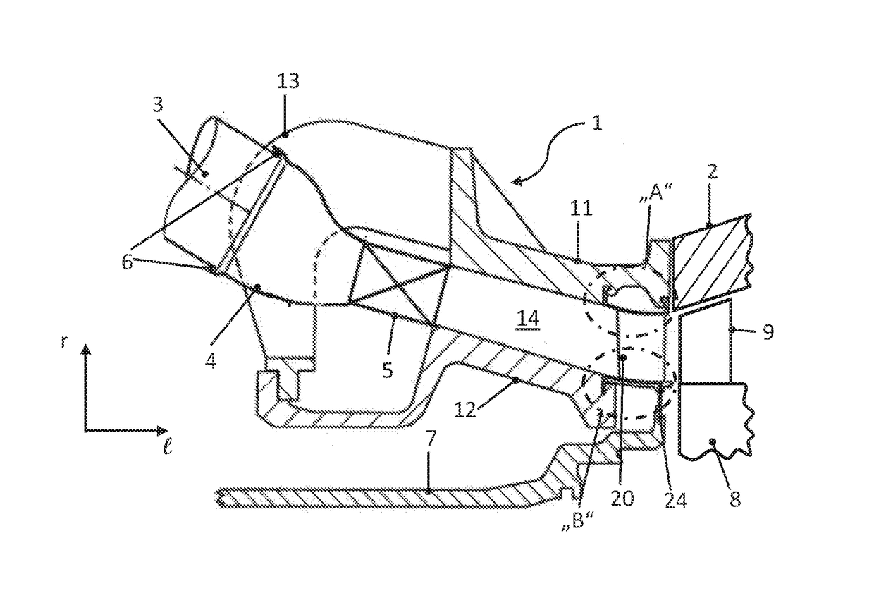
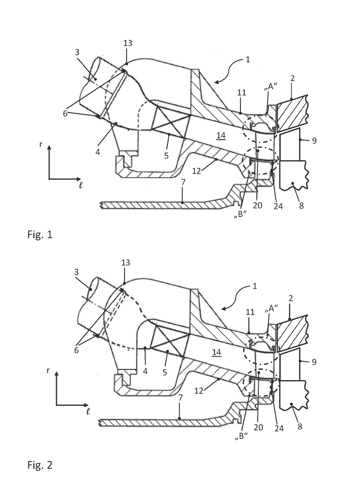
[0045]FIGS. 1 and 2 depict sections of a part of an exemplary gas turbine engine taken at different circumferential positions. The gas turbine engine defines a radial direction r and an axial direction e. A main working fluid flow direction extends essentially along the axial direction e, and is generally directed from a compressor, not shown in the present depiction, to an expansion turbine. The gas turbine engine comprises a vane carrier unit 1, which in turn comprises an outer wall structure 11, an inner wall structure 12, and a bridg...


PUM


Abstract

A turboengine as disclosed includes an outer wall structure and an inner wall structure, wherein the inner wall structure is provided at a radially inner position with respect to the outer wall structure, and each of the wall structures has a surface, the surfaces being arranged facing each other in the radial direction. At least one guide vane member includes at least one airfoil, a radially inner end and a radially outer end. The inner wall structure and the outer wall structure are jointly provided as a vane carrier unit, wherein the inner wall structure and the outer wall structure are fixedly connected to each other by at least one bridging member extending between the inner wall structure and the outer wall structure.

Description

PRIORITY CLAIM[0001]This application claims priority from European Patent Application No. 16164575.9 filed on Apr. 8, 2016, the disclosure of which is incorporated by reference.TECHNICAL FIELD[0002]The present disclosure relates to a turboengine as set forth in claim 1. It further relates to a guide vane carrier unit for a turboengine.BACKGROUND OF THE DISCLOSURE[0003]The stationary first or inlet guide vanes of an expansion turbine of a turboengine, and in particular of a gas turbine engine, are typically supported at an outer end and an inner, or hub side, end, in order to support the axial forces resulting from the absolute pressure differential over the inlet guide vane at the high temperatures typically being present. The vanes are generally provided as vane members, wherein a vane member comprises one or more airfoils, which extend between two platforms. An inner or hub side platform of the vane member constitutes the inner or hub side end of a vane member, and an outer platfo...

Claims


Application Information

Patent Timeline
IPC IPC(8): F01D9/04F01D5/02F23R3/00F02C3/14
CPCF01D9/042F02C3/14F01D9/041F05D2240/35F23R3/002F05D2220/32F01D5/02F01D9/023F05D2220/321F05D2220/3212F01D25/28F02C7/20F23R3/60F05D2260/30F23R2900/00017Y02E20/16F23R2900/00012Y02T50/60
Inventor BENZ, URS
Owner ANSALDO ENERGIA SWITZERLAND AG
Features
  • Generate Ideas
  • Intellectual Property
  • Life Sciences
  • Materials
  • Tech Scout
  • Unparalleled Data Quality
  • Higher Quality Content
  • 60% Fewer Hallucinations
Learn More