Friction plate

a technology of friction plate and friction plate, which is applied in the field of friction plate, can solve the problems of system problem inherent in system, etc., and achieve the effect of improving the inflow of oil, reducing the loss of performance of wet-running friction system, and improving the cooling of friction pla

Active Publication Date: 2017-10-12
MIBA FRICTEC
View PDF0 Cites 0 Cited by
  • Summary
  • Abstract
  • Description
  • Claims
  • Application Information

AI Technical Summary

Benefits of technology

[0013]Furthermore, a transition from the first oil grooves to the second oil grooves may be at least partially chamfered. The transfer of the lubricating oil from the first to the third oil groove can be improved as a result, thereby enabling the lubricant to be fed away more effectively.
[0014]To improve the inflow of oil into the first oil grooves, the first oil grooves may be provided with a cross-section which becomes wider in the direction towards the radially outer end face of the friction lining.
[0015]Based o

Problems solved by technology

However, wet-running friction systems also have a problem inherent in the s

Method used


Image

  • Friction plate
  • Friction plate
  • Friction plate

Examples


Embodiment Construction

[0022]Firstly, it should be pointed out that the same parts described in the different embodiments are denoted by the same reference numbers and the same component names and the disclosures made throughout the description can be transposed in terms of meaning to same parts bearing the same reference numbers or same component names. Furthermore, the positions chosen for the purposes of the description, such as top, bottom, side, etc., relate to the drawing specifically being described and can be transposed in terms of meaning to a new position when another position is being described.

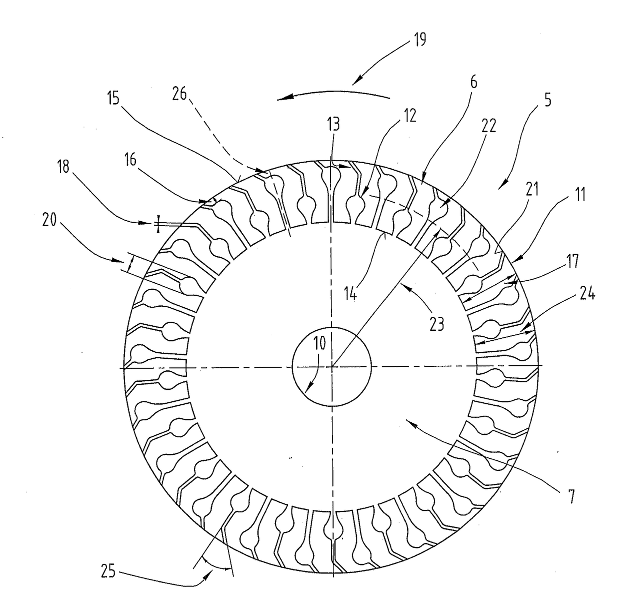
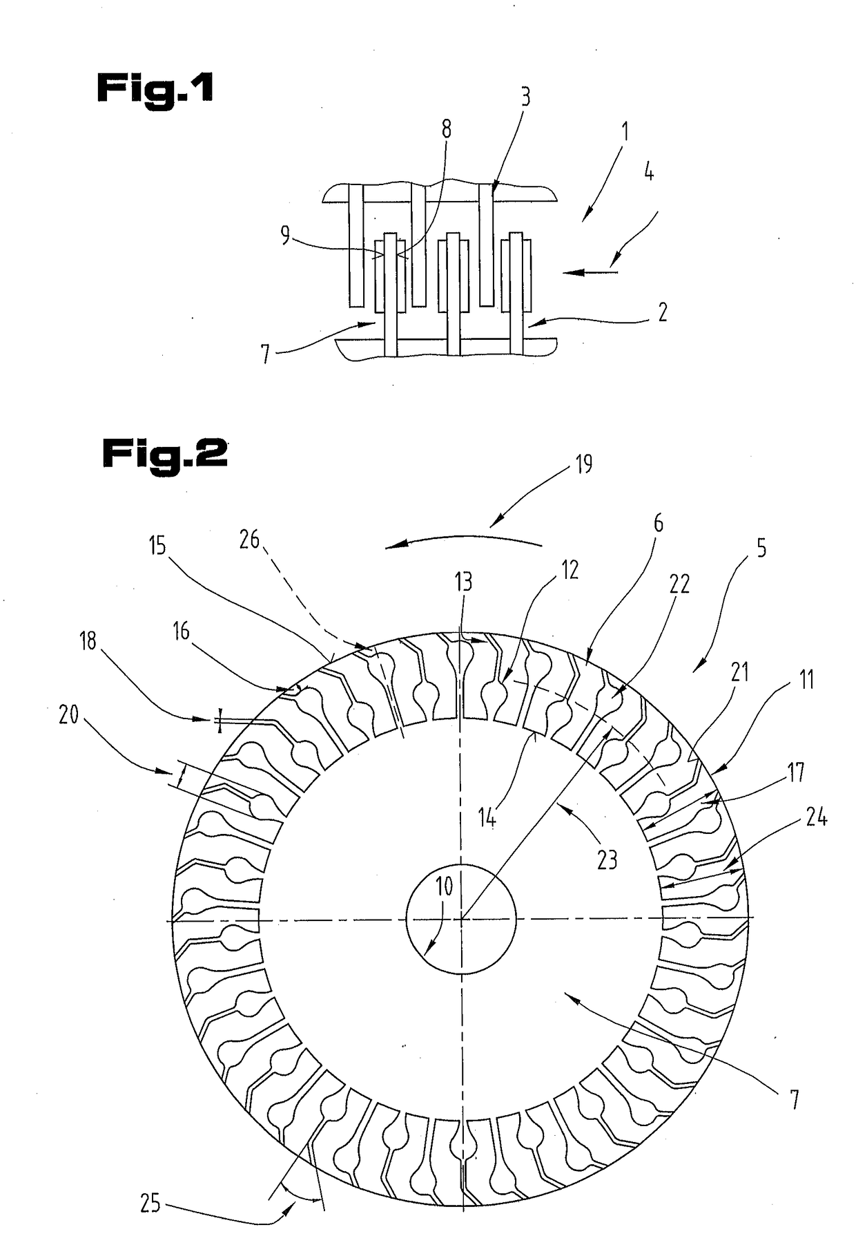
[0023]FIG. 1 illustrates a detail of a wet-running multi-plate clutch 1. The multi-plate clutch 1 has a number of inner plates 2 and a number of outer plates 3. The inner plates 2 are disposed in an alternating arrangement with the outer plates 3 in an axial direction 4. The inner plates 2 can be moved in the axial direction 4 relative to the outer plates 3 by an appropriate actuating mechanism so that a...


PUM


Abstract

A friction plate for wet-running applications includes an annular main body having a first and a second surface. A friction lining having first oil grooves and second oil grooves is disposed on at least one of the first and the second surfaces. The first oil grooves extend from a radially inner end face of the friction lining in the direction towards a radially outer end face of the friction lining and terminate at a distance short of the radially outer end face, and the second oil grooves are disposed directly adjoining the first oil grooves in the radial direction and have a smaller maximum width in the circumferential direction than the first oil grooves. The first oil grooves are provided with a cross-sectional widening in the region of a radially outer end. The cross-sectional widenings of the first oil grooves are disposed at different radial heights.

Description

CROSS REFERENCE TO RELATED APPLICATIONS[0001]Applicant claims priority under 35 U.S.C. §119 of Austrian Application No. GM 50058 / 2016 filed on Apr. 8, 2016, the disclosure of which is incorporated by reference.BACKGROUND OF THE INVENTION1. Field of the Invention[0002]The invention relates to a friction plate for wet-running applications comprising an annular main body having a first and a second surface in the axial direction, and on which a friction lining having first oil grooves and second oil grooves is disposed on at least one of the first and the second surfaces, and the first oil grooves extend from a radially inner end face of the friction lining in the direction towards a radially outer end face of the friction lining and terminate at a distance short of the radially outer end face, and the second oil grooves are disposed adjoining the first oil grooves in the radial direction and have a smaller maximum width in the circumferential direction than the first oil grooves, and ...

Claims


Application Information

Patent Timeline
IPC IPC(8): F16D13/64F16D13/74F16D13/72
CPCF16D13/648F16D2069/004F16D13/74F16D13/72
Inventor HARTNER, GERHARDMARKOWSKY, FLORIANSTURM, THOMAS
Owner MIBA FRICTEC
Why Eureka
Try Eureka