Optical receiver, portable electronic device, and method of producing optical receiver

Active Publication Date: 2017-10-12
SHARP KK
View PDF5 Cites 5 Cited by
  • Summary
  • Abstract
  • Description
  • Claims
  • Application Information

AI Technical Summary

Benefits of technology

[0028]An aspect of the present invention has an effect of providing an optical receiver that can realize a reduction in the variation in sensitivity in the ultraviolet li

Problems solved by technology

In recent years, the destruction of the ozone layer has been progressing by discharging chemicals containing fluorocarbon or chlorine that have been used in, for example, refrigerators and air conditioners into the atmosphere, resulting in an increase in the amount of ultraviolet light falling onto the ground.
Ultraviolet light has a short wavelength and thereby have high light energy and

Method used


Image

  • Optical receiver, portable electronic device, and method of producing optical receiver
  • Optical receiver, portable electronic device, and method of producing optical receiver
  • Optical receiver, portable electronic device, and method of producing optical receiver

Examples


embodiment 1

[0042]An embodiment of the present invention can be described based on FIGS. 1 to 7 as follows.

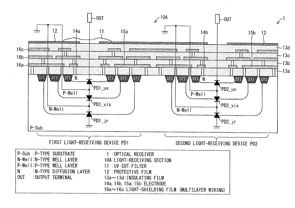
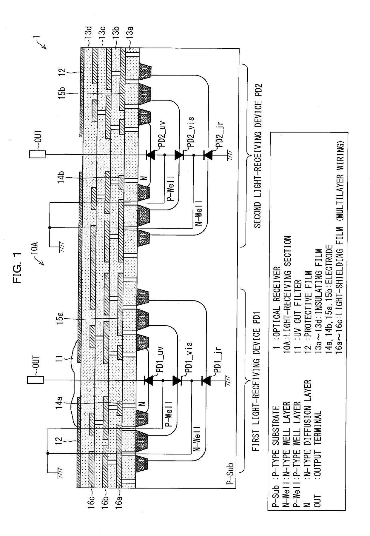
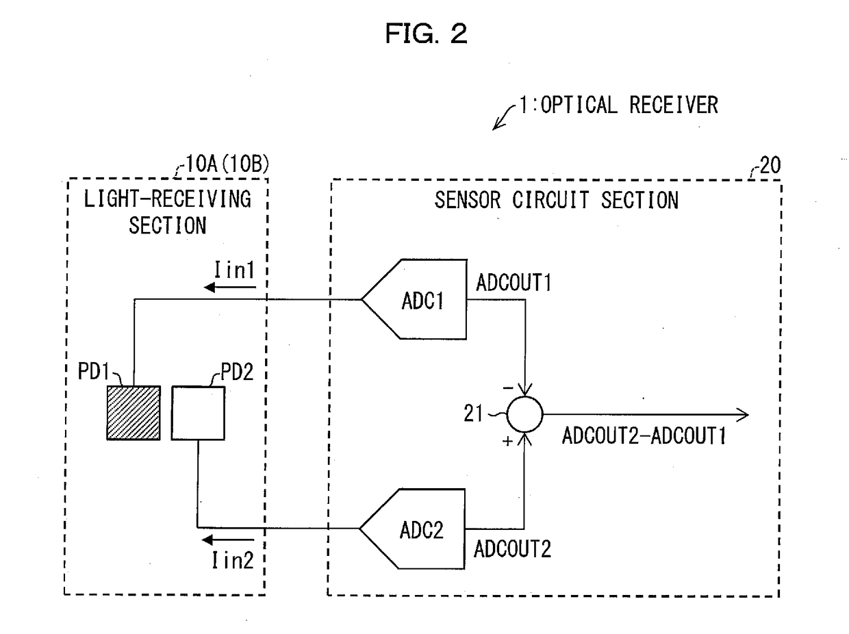
[0043]An optical receiver 1 of the embodiment will be described based on FIGS. 1 to 3. FIG. 1 is a cross-sectional view illustrating the structure of a light-receiving section 10A of the optical receiver 1 according to the embodiment. FIG. 2 is a block diagram illustrating the structure of the optical receiver 1 of the embodiment. FIG. 3 is a plan view illustrating the structure of the light-receiving section 10A of the optical receiver 1.

[0044]The optical receiver 1 of the embodiment is, as shown in FIG. 2, a light sensor including a light-receiving section 10A for allowing photocurrent to flow by incidence of light and a sensor circuit section 20 for detecting the intensity of the light based on the photocurrent. The optical receiver 1 can be loaded on a portable electronic device, such as a smartphone, as a photoelectric conversion device. The components will now be described one by one...

embodiment 2

[0121]Another embodiment of the present invention can be described based on FIGS. 2, 3, and 8 to 11 as follows. The structures other than those described in this embodiment are the same as those in Embodiment 1. In addition, for convenience of explanation, members having the same functions as those of the members shown in the drawings of Embodiment 1 are denoted by the same reference symbols, and the descriptions thereof are omitted.

[0122]The optical receiver 1 of this embodiment includes, as shown in FIGS. 2 and 3, a light-receiving section 10B as in the light-receiving section 10A described in Embodiment 1. Incidentally, in FIGS. 2 and 3, the function of the light-receiving section 10B is the same as that of the light-receiving section 10A, and the description thereof is therefore omitted.

[0123]The light-receiving section 10B of the optical receiver 1 in the embodiment differs from the light-receiving section 10A of the optical receiver 1 in Embodiment 1 in that, as shown in FIG. ...

embodiment 3

[0141]Further another embodiment of the present invention can be described as follows. The structures other than those described in this embodiment are the same as those in Embodiments 1 and 2. In addition, for convenience of explanation, members having the same functions as those of the members shown in the drawings of Embodiments 1 or 2 are denoted by the same reference symbols, and the descriptions thereof are omitted.

[0142]The light-receiving section 10A of Embodiment 1 and the light-receiving section 10B of Embodiment 2 are each composed of triple diffusion layers. Specifically, an N-type well layer N_well being a second conductivity-type N-type diffusion layer as a first diffusion layer is formed on a P-type substrate P_sub; a first conductivity-type P-type substrate P_sub as a second diffusion layer is formed in the first diffusion layer; and an N-type diffusion layer N as a second conductivity-type third diffusion layer is formed in the second diffusion layer.

[0143]However, ...


PUM


Abstract

Provided are an optical receiver that can realize a reduction in the variation of sensitivity in the ultraviolet light region and a reduction in noise in the visible light region and the infrared light region, a portable electronic device, and a method of producing an optical receiver. The first light-receiving device (PD1) and the second light-receiving device (PD2) of the optical receiver (1) are each constituted by forming a second conductivity-type N-type well layer (N_well) on a first conductivity-type P-type substrate (P_sub), forming a first conductivity-type P-type well layer (P_well) in the N-type well layer (N_well), and forming a second conductivity-type N-type diffusion layer (N) in the P-type well layer (P_well). The P-type substrate P_sub, the N-type well layer (N_well), and the P-type well layer (P_well) are electrically at the same potential or are short-circuited.

Description

TECHNICAL FIELD[0001]The present invention relates to an optical receiver, a portable electronic device, and a method of producing an optical receiver, more specifically, an optical receiver that is used as an ultraviolet sensor and a portable electronic device including the optical receiver, and a method of producing an optical receiver.BACKGROUND ART[0002]In recent years, the destruction of the ozone layer has been progressing by discharging chemicals containing fluorocarbon or chlorine that have been used in, for example, refrigerators and air conditioners into the atmosphere, resulting in an increase in the amount of ultraviolet light falling onto the ground. Ultraviolet light has a short wavelength and thereby have high light energy and damage, for example, the skin.[0003]Ultraviolet light is classified, depending on the wavelength, into UV-A (315 to 400 nm), UV-B (280 to 315 nm), and UV-C (100 to 280 nm). UV-C having the shortest wavelength in ultraviolet light is significantl...

Claims


Application Information

Patent Timeline
IPC IPC(8): H01L27/146H01L31/101
CPCH01L27/14643H01L27/14625H01L31/101H01L31/02165H01L31/1013H01L27/1446G01J1/1626G01J2001/1657G01J1/429G01J1/0488G01J1/4228
Inventor UCHIHASHI, MASAAKINATSUAKI, KAZUHIROUCHIDA, MASAYOTAKIMOTO, TAKAHIRO
Owner SHARP KK
Why Eureka
Try Eureka