Cable connector and carrier module thereof

a carrier module and cable connector technology, applied in the direction of coupling contact members, coupling device connections, two-part coupling devices, etc., can solve problems such as unstable connection between positioning members and circuit boards, and achieve the effect of effectively solving problems

Active Publication Date: 2017-10-12
STARCONN ELECTRONICS SU ZHOU CO LTD
View PDF0 Cites 3 Cited by
  • Summary
  • Abstract
  • Description
  • Claims
  • Application Information

AI Technical Summary

Benefits of technology

[0003]The instant disclosure provides a cable connector and a carrier module thereof

Problems solved by technology

However, the edge of the positioning member is fixed on the surface of the circuit board by using spo

Method used


Image

  • Cable connector and carrier module thereof
  • Cable connector and carrier module thereof
  • Cable connector and carrier module thereof

Examples


first embodiment

[0025]Please refer to FIGS. 1 through 10, which show a first embodiment of the instant disclosure. References are hereunder made to the detailed descriptions and appended drawings in connection with the instant invention. However, the appended drawings are merely shown for exemplary purposes, rather than being used to restrict the scope of the instant invention.

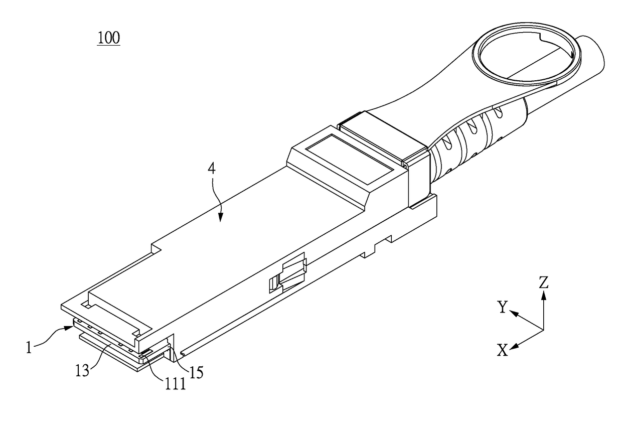
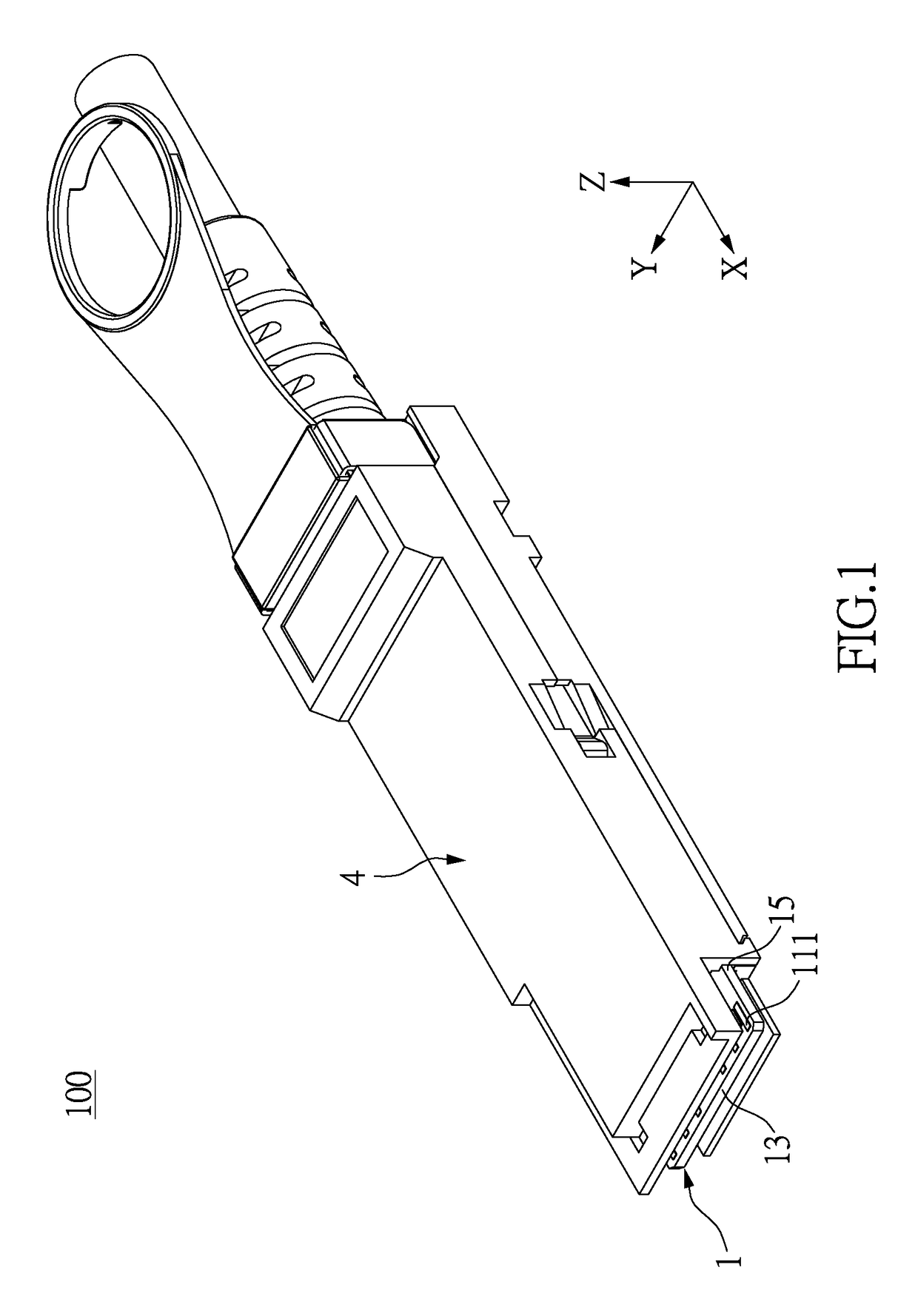
[0026]Please refer to FIGS. 1 through 4, which show a cable connector 100 of the instant embodiment including a circuit board 1, a connecting clip 2, a plurality of conductive cables 3, and a case 4 receiving the circuit board 1, the connecting clip 2, and the conductive cables 3. A front end portion of the circuit board 1 is exposed from the case 4. The conductive cables 3 are positioned on a rear end portion of the circuit board 1 by using the connecting clip 2.

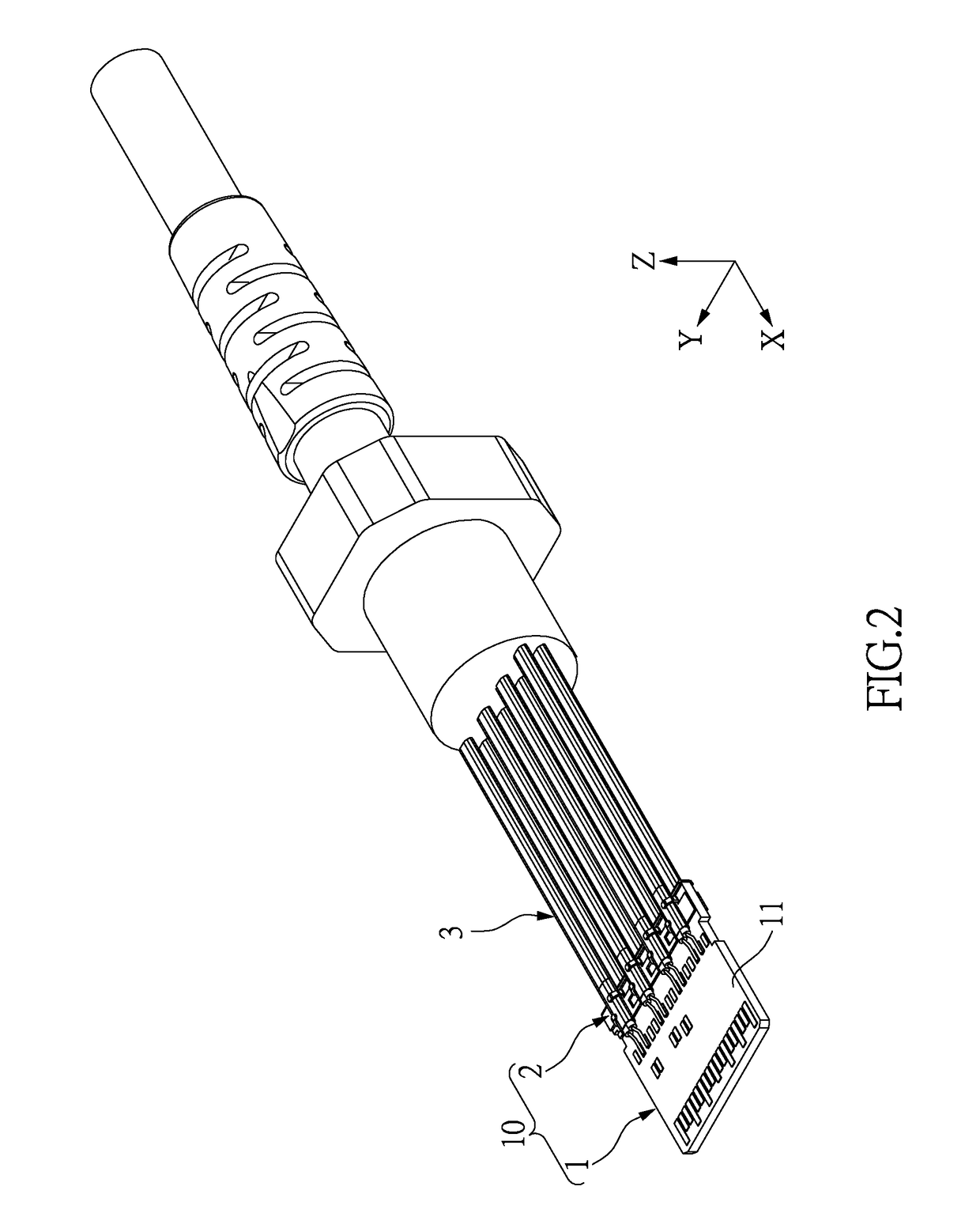
[0027]FIGS. 2 through 10 do not show the case 4 in order to more clearly show the inner construction of the cable connector 100, and each figure shows an axis X, an ...

second embodiment

[0039]Please refer to FIGS. 11 and 12, which show a second embodiment. The second embodiment is similar to the first embodiment, the different features between the two embodiments being the construction of the connecting clip 2 and the corresponding portion of the circuit board 1.

[0040]Specifically, the circuit board 1 is a multi-layer construction and includes a first insulating layer 16, a second insulating layer 17, and a grounding layer 18 arranged between the first insulating layer 16 and the second insulating layer 17. The first surface 11 in the instant embodiment includes an outer surface of the first insulating layer 16, the touching pads 111, and the welding pads 112. The second surface 12 in the instant embodiment includes an outer surface of the second insulating layer 17, the touching pads 121, and the welding pads 122.

[0041]Moreover, at least one hole 113 is inwardly formed on the first surface 11 of the circuit board 1, and the circuit board 1 has at least one conduct...

third embodiment

[0045]Please refer to FIGS. 13 and 14, which show a third embodiment. The third embodiment is similar to the first and second embodiments, and the different features of the third embodiment compared to the first and second embodiments are the construction of the connecting clip 2 and the corresponding portion of the circuit board 1.

[0046]Specifically a hole 113′ is inwardly formed on one of the side edges 15 of the circuit board 1 penetrating through the circuit board 1 from the first surface 11 to the second surface 12. The circuit board 1 has a conductive extension 114 coated on an inner wall defining the hole 113′. The connecting clip 2 has a conductive portion 24′ curvedly extended from one of the clamping sheets 212, and the conductive portion 24′ is formed as an elastic arm. The conductive portion 24′ of the connecting clip 2 is inserted into the hole 113′ of the circuit board 1 and abuts against the conductive extension 114 arranged in the hole 113′.


PUM


Abstract

A carrier module of a cable connector includes a circuit board and a connecting clip clamping the circuit board. The circuit board has a first surface and a second surface. The connecting clip has a clamping portion and a plurality of positioning arms. The clamping portion has a connecting sheet and two clamping sheets curvedly extended from the connecting sheet. The clamping sheets are respectively abutted against the first and second surfaces. The positioning arms are respectively connected to the clamping sheets and respectively arranged at two opposite sides of the clamping portion. The positioning arms are respectively configured to fix a plurality of cables disposed on the clamping sheets. Thus, the carrier module of the instant disclosure provides a positioning effect for the cables by the connecting clip fixed firmly on the circuit board with good common grounding performance. Besides, the instant disclosure also provides a cable connector.

Description

BACKGROUND OF THE INVENTION1. Field of the Invention[0001]The instant invention relates to a connector and, in particular, to a cable connector and a carrier module thereof.2. Description of Related Art[0002]The conventional cable connector includes a circuit board, a plurality of cables, and a positioning member. One end of each cable is welded on a surface of the circuit board, and an edge of the positioning member is welded on the surface of the circuit board to press the cables, such that the cables are clamped by the circuit board and the positioning member. However, the edge of the positioning member is fixed on the surface of the circuit board by using spot welding merely, so the connection between the positioning member and the circuit board is unstable. Accordingly, when any cable and the circuit board are pulled to generate a shearing force, the positioning member is easily separated from the surface of the circuit board because of the shearing force.SUMMARY OF THE INVENTI...

Claims


Application Information

Patent Timeline
IPC IPC(8): H01R13/58H01R13/26H01R12/53
CPCH01R13/5804H01R13/26H01R12/53H01R13/6585H01R13/6596H01R13/6658H01R24/60H01R13/65914
Inventor PAO, CHUNG-NANLIN, YU-HSIUNGLAI, YI-GUANGHSU, MING-CHUNWU, KAI
Owner STARCONN ELECTRONICS SU ZHOU CO LTD
Why Eureka
Try Eureka