Exhaust gas purification device

Active Publication Date: 2017-10-19
CATALER CORP
View PDF3 Cites 23 Cited by
  • Summary
  • Abstract
  • Description
  • Claims
  • Application Information

AI Technical Summary

Benefits of technology

[0013]In a preferred aspect of the exhaust gas purification device disclosed herein, the coating amount of the upstream catalyst layer per L of volume of the substrate is smaller than the coating amount of the downstream catalyst layer per L of volume of the substrate. By setting thus the coating amount of the upstream catalyst layer to be smaller than the coating amount of the downstream catalyst layer, the exhaust gas flows preferentially in the upstream portion of the partition wall. As a result, the flow of exhaust gas from the inlet cell up to the outlet cell becomes smoother, and pressure loss can be further reduced. In a preferred aspect, the coating amount of the upstream catalyst layer per L of volume of the substrate is 60 g/L to less than 99.9 g/L. The above-described effect can be brought out yet better when the coating amount upstream catalyst layer lies within the above range.
[0014]In a preferred aspect of the exhaust gas purification device disclosed herein, the upstream catalyst layer is formed in a portion corresponding to 20% to 80% of the length of the substrate, from the exhaust gas inflow end section of the substrate towards the downstream side. Further, the downstream catalyst layer is formed in a portion corresponding to 20% to 80% of the length of the substrate, from an exhaust gas outflow end section of the substrate towards the upstream side. Within these ranges of the lengths of the upstream catalyst layer and of the downstream catalyst layer, it becomes possible to achieve a greater degree of enhancement of purification performance and reduction in pressure loss.
[0015]In a preferred aspect of the exhaust gas purification device disclosed herein, the upstream catalyst layer contains Rh as the noble metal, and the downstream catalyst layer contains Pt and/or Pd as the noble metal. By virtue of the above configuration, harmful components in the exhaust gas can be purified efficiently all at once, and exhaust gas purification performance can be further enhanced.
[0016]In a preferred aspect of the ex

Problems solved by technology

The purification performance on exhaust gas may drop as a result.
The Rh layer is disposed outside the partition wall, however, and thus exhau

Method used


Image

  • Exhaust gas purification device
  • Exhaust gas purification device
  • Exhaust gas purification device

Examples


Example

TEST EXAMPLE 1

[0070]Test examples pertaining to the present invention will be explained next, but the invention is not meant to be limited to the test examples illustrated below.

[0071]

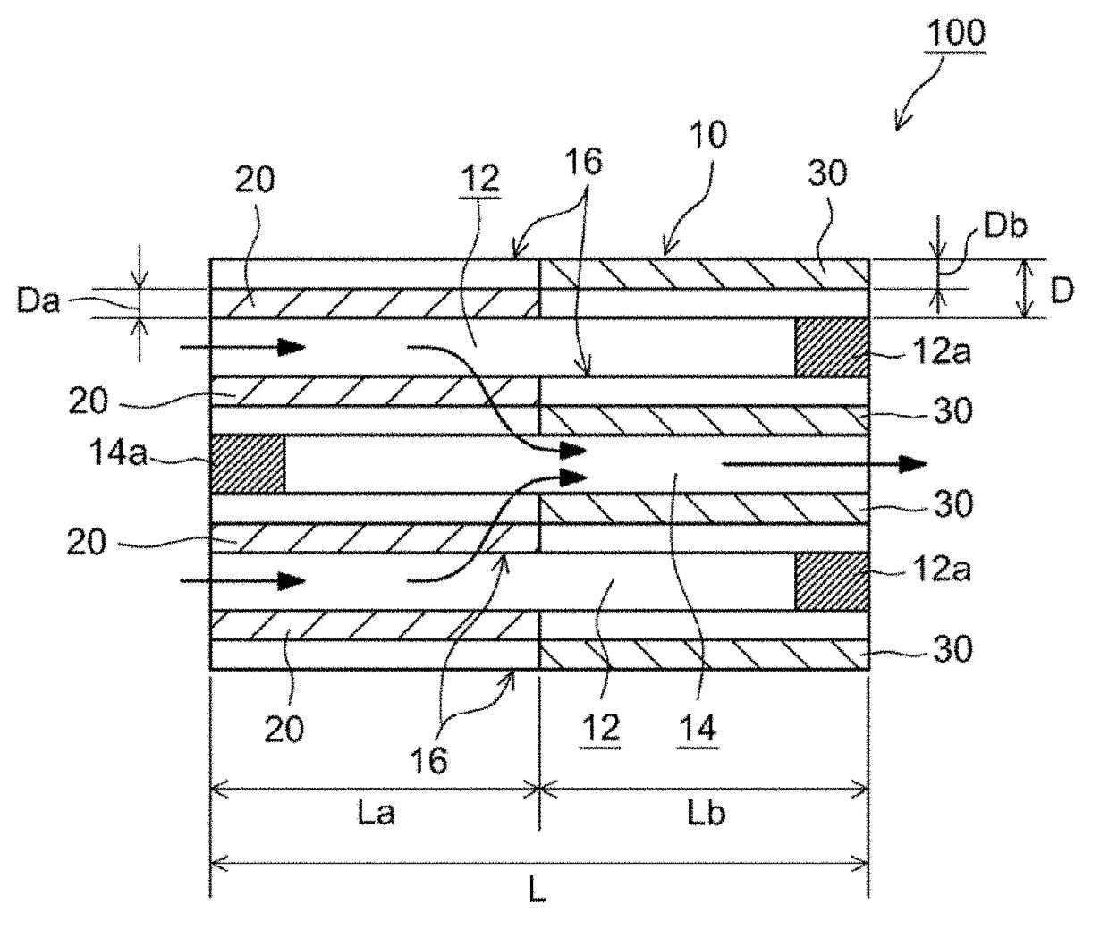
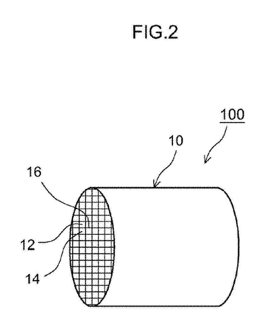
[0072]Herein alumina as a carrier for upstream catalyst layer formation was prepared and was impregnated with a Rh nitrate solution as a noble metal catalyst solution, followed by evaporation to dryness, to prepare a Rh / alumina carrier powder supporting 0.8 mass % of Rh. A slurry for upstream catalyst layer formation was then prepared through mixing of 36.9 parts by mass of the Rh / alumina carrier powder, 36.61 parts by mass of a ceria-zirconia complex oxide, and deionized water. Next the slurry was applied through suction onto a portion of a cordierite substrate (wall flow-type substrate illustrated in FIG. 2 and FIG. 3: diameter 103 mm, total length 100 mm) corresponding to 50% of the length L of the substrate from the exhaust gas inflow end section towards the downstream side, and onto a portion corr...

Example

TEST EXAMPLE 2

[0092]The test below was performed in order to check the influence exerted on pressure loss by increases and decreases in the upstream catalyst layer inside the partition wall. Specifically, particulate filters were produced having dissimilar ratios of the upstream catalyst layer present inside the partition wall and of the upstream catalyst layer present outside (surface) of the partition wall. The coating amount of total upstream catalyst layer was set to be constant, at 70 g / L.

[0093]In Sample 1, as described above, the upstream catalyst layer is disposed only inside the partition wall. That is, taking the total coating amount of upstream catalyst layer as 100%, as given in Table 2, then the coating amount fraction present inside the partition wall is 100%. In Sample 12, by contrast, the ratio of coating amount inside and outside the partition wall was adjusted so that the coating amount fraction present inside the partition wall was 96% and the coating amount fracti...


PUM

PropertyMeasurementUnit
Fractionaaaaaaaaaa
Fractionaaaaaaaaaa
Fractionaaaaaaaaaa

Abstract

An exhaust gas purification device of the present invention is provided with: a substrate of wall flow structure having an inlet cell, an outlet cell and a porous partition wall; an upstream catalyst layer, provided inside the partition wall and disposed in an upstream portion of the substrate including an exhaust gas inflow end section; and a downstream catalyst layer, provided inside the partition wall and disposed in a downstream portion of the substrate including an exhaust gas outflow end section. The upstream catalyst layer and the downstream catalyst layer each contain a carrier and at least one noble metal from among Pt, Pd and Rh, supported on the carrier. The noble metal in the upstream catalyst layer and the noble metal in the downstream catalyst layer are different from each other.

Description

TECHNICAL FIELD[0001]The present invention relates to an exhaust gas purification device. More particularly, the present invention relates to an exhaust gas purification device that purifies exhaust gas emitted by an internal combustion engine such as a gasoline engine.[0002]The present application claims priority based on Japanese Patent Application No. 2014-208151, filed on Oct. 9, 2014, and Japanese Patent Application No. 2015-136905, filed on Jul. 8, 2015, the entire contents whereof are incorporated in the present description by reference.BACKGROUND ART[0003]Generally, exhaust gas emitted by internal combustion engines contains particulate matter (PM) having carbon as a main component, as well as ash made up of unburned components, which are known to give rise to air pollution. Regulations concerning emissions of particulate matter have therefore become stricter year after year, alongside regulations on harmful components in exhaust gas such as hydrocarbons (HC), carbon monoxid...

Claims


Application Information

Patent Timeline
IPC IPC(8): B01D53/94B01J35/04B01J35/00F01N3/28B01J23/63F01N13/00
CPCB01D53/9472B01D53/9454B01J35/0006B01J23/63B01J35/04F01N2370/02F01N3/28B01D2255/1025B01D2255/1021B01D2255/1023F01N13/009B01D53/94B01D53/945F01N3/035B01D2255/9032B01D2255/9155F01N2330/06F01N2510/0682B01D2255/905B01J37/0244B01J23/40Y02T10/12
Inventor OHASHI, TATSUYASAKAGAMI, SHINGOITO, TSUYOSHIONOE, RYOTAMIYOSHI, NAOTOTAKEUCHI, MASAHIKOSATO, AKEMI
Owner CATALER CORP
Why Eureka
Try Eureka