Bead core covering method and bead core covering device

a technology of bead core and bead core, which is applied in the direction of tyres, domestic applications, other domestic articles, etc., can solve the problems of deterioration of the precision of the cover rubber, and achieve the effect of high precision

Inactive Publication Date: 2017-10-19
TOYO TIRE & RUBBER CO LTD
View PDF4 Cites 3 Cited by
  • Summary
  • Abstract
  • Description
  • Claims
  • Application Information

AI Technical Summary

Benefits of technology

[0044]According to the structure mentioned above, it is possible to extrude the rubber sheet at high precision since the thickness of the rubber sheet can be controlled by the gap between the mouth piece and the peripheral projection of the rotary drum.

Problems solved by technology

Further, in the conventional method, a precision of the cover rubber is deteriorated due to a tension at a time of winding around the bobbin, a tension at a time of peeling off the film, a tension at a time of conveying by the festooner, and a dimensional change caused by constriction in a convey line.

Method used


Image

  • Bead core covering method and bead core covering device
  • Bead core covering method and bead core covering device
  • Bead core covering method and bead core covering device

Examples


first embodiment

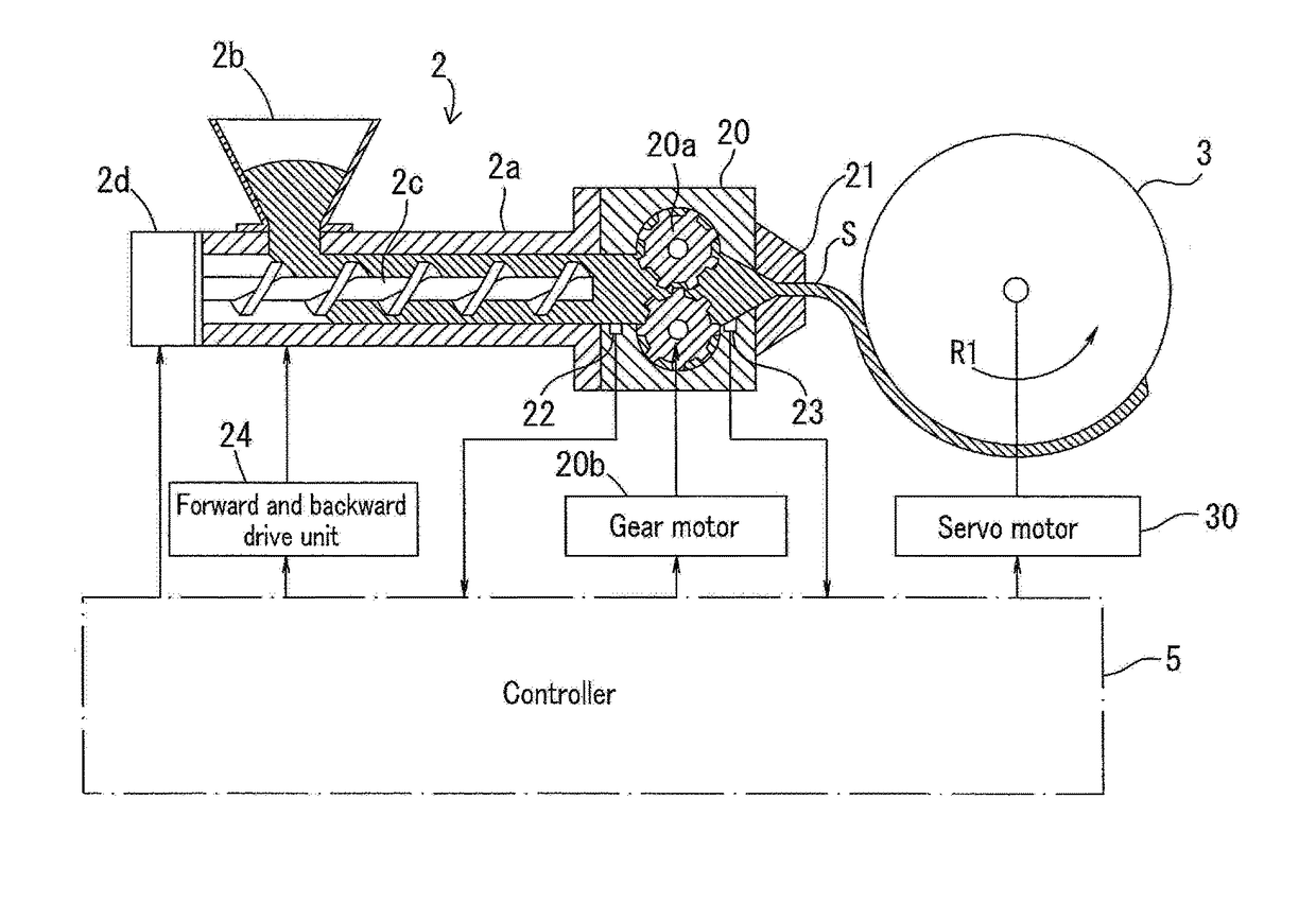
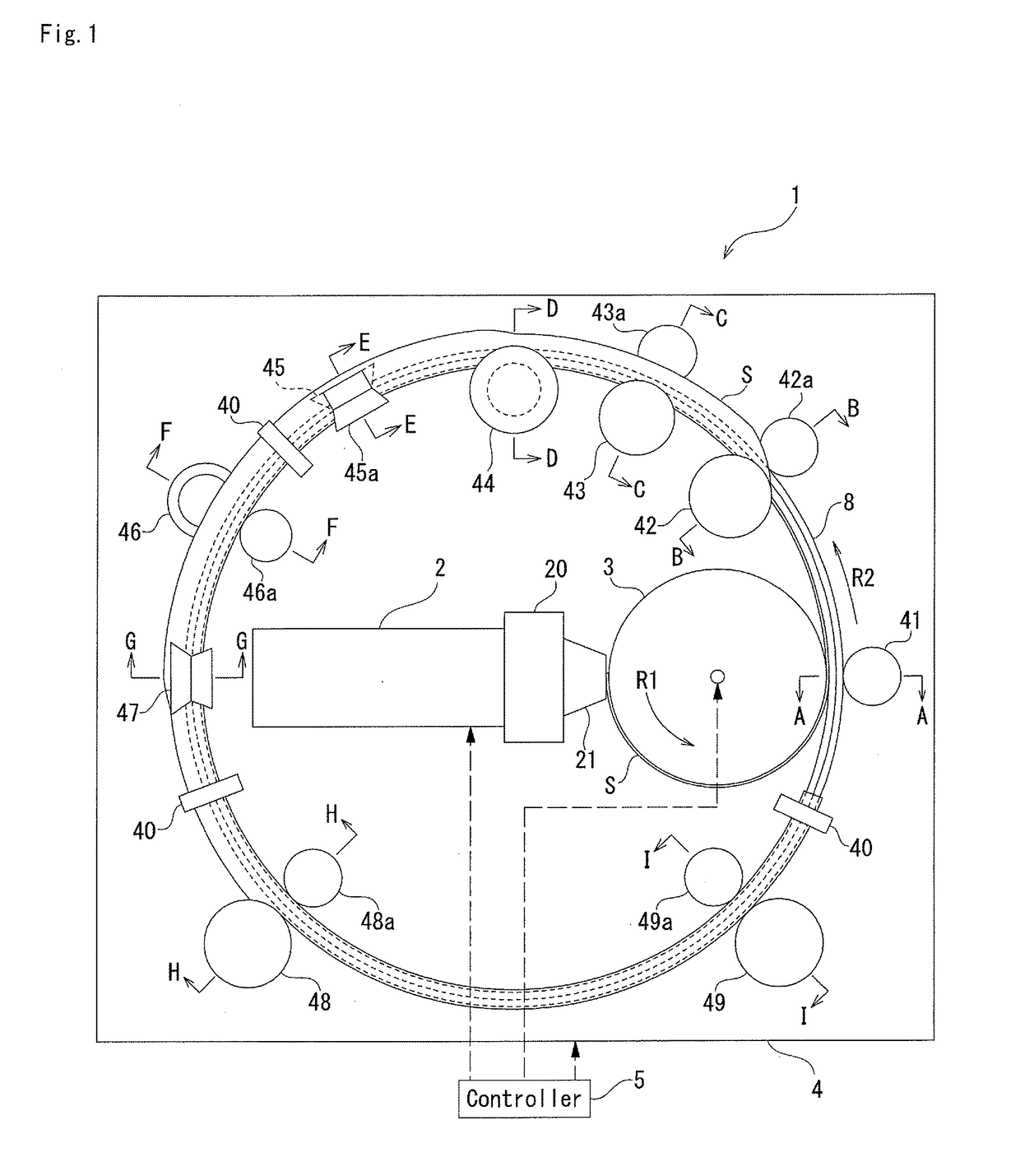
[0074]FIG. 1 is a schematic view showing an example of a structure of a bead core covering device 1. The bead core covering device 1 is provided with an extruding machine 2, a rotary drum 3, a wrapping device 4, and a controller 5 which controls the extruding machine 2, the rotary drum 3 and the wrapping device 4.

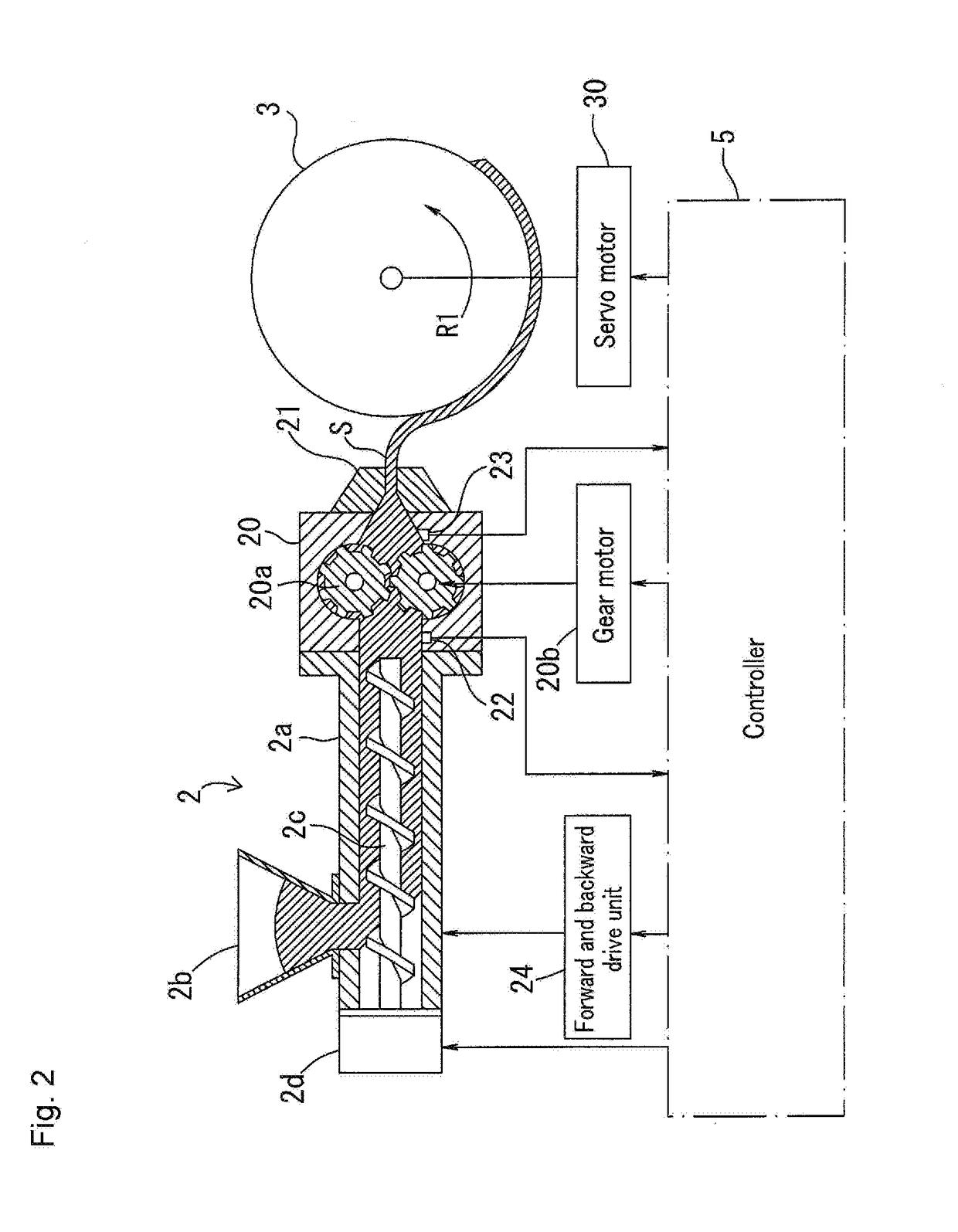
[0075]FIG. 2 is a schematic view showing an example of a structure of the extruding machine 2 and the rotary drum 3. The extruding machine 2 has a cylindrical barrel 2a, a hopper 2b which is connected to a supply port of the barrel 2a, a screw 2c which mixes rubber and discharges the rubber to a leading end side, and a screw motor 2d which rotatably drives the screw 2c. The rotating speed of the screw motor 2d is controlled by the controller 5 as mentioned later.

[0076]A gear pump 20 is connected to a leading end side in an extruding direction of the extruding machine 2, and a leading end side of the gear pump 20 is connected to a mouth piece 21. A rubber material mixed by t...

second embodiment

[0113]FIG. 6 is a schematic view showing an example of a structure of a bead core covering device 1. The bead core covering device 1 is provided with an extruding machine 2, a rotary drum 3, a wrapping device 4, and a controller 5 which controls the extruding machine 2, the rotary drum 3 and the wrapping device 4.

[0114]FIG. 7 is a view of the rotary drum 3 as seen from a direction which is perpendicular to the rotation axis. A peripheral groove 31 extending along the peripheral direction is formed in the outer surface of the rotary drum 3. The peripheral groove 31 is formed into an inverse trapezoidal shape in across sectional shape in the axial direction of the rotary drum 3. The peripheral groove 31 is provided with a groove bottom surface 31a, and groove wall surfaces 31b and 31c which extend from both sides of the groove bottom surface 31a.

[0115]The wrapping device 4 supports the bead core 8 in such a manner that an outer peripheral surface of the rotary drum 3 and an outer sur...

third embodiment

[0139]The second embodiment as above describes the example that the rubber sheet S wound onto the outer surface of the rotary drum 3 is attached to the inner peripheral surface (the lower surface 8a) of the rotating bead core 8 from the leading end portion of the portion which is positioned in the groove bottom surface 31a of the peripheral groove 31. However, the structure is not limited thereto.

[0140]As shown in FIG. 9A, a bead core covering device 1 according to a third embodiment may include: an extruding machine 2 which extrudes the rubber sheet S; a rotary drum 3 around which the rubber sheet S extruded out of the extruding machine 2 is wound; a wrapping device 4 which supports a bead core 8 so that an outer surface of the rotary drum 3 and an outer peripheral surface of the bead core 8 come close to each other at a position on a downstream side in a rotating direction of the rotary drum 3 from the extruding machine 2, and which rotates the supported bead core 8; and a control...


PUM

PropertyMeasurementUnit
outer diameteraaaaaaaaaa
inner diameteraaaaaaaaaa

Abstract

A bead core covering method for covering an annular bead core with a belt-like rubber sheet includes winding the rubber sheet extruded by an extruding machine via a mouth piece around an outer peripheral surface of a rotary drum from a leading end portion, attaching a part in a width direction of the rubber sheet on the outer peripheral surface of the rotary drum to an outer surface of the bead core, which rotates, from the leading end portion before the rubber sheet is wound over an entire periphery of the outer peripheral surface of the rotary drum, and wrapping a remaining portion in the width direction of the rubber sheet attached to the outer surface of the bead core along a cross-sectional shape of the bead core.

Description

BACKGROUND OF THE INVENTIONField of the Invention[0001]The present invention relates to a bead core covering method and a bead covering device for covering an annular bead core with a belt-like rubber sheet.Description of the Related Art[0002]Generally, an annular bead core formed by covering with rubber a convergence body such as a steel wire is arranged in a bead portion of a pneumatic tire. In some cases, a surface of the bead core is covered with a thin rubber sheet for integrating the steel wire and the like. The rubber sheet may be called as a cover rubber or a bead cover rubber.[0003]The following Patent Document 1 describes a bead core covering device and a bead core covering method for covering a surface of a bead core with a sheet member made of a rubber. The bead core covering device of Patent Document 1 is provided with a supply portion which supplies to a rotating bead core a belt-like sheet member covering a surface of the bead core, a shaping roller which rotates alon...

Claims


Application Information

Patent Timeline
Patent Type & Authority Applications(United States)
IPC IPC(8): B29D30/50
CPCB29D30/50B29D2030/482
Inventor HASHIMOTO, YOSHIKIMIYAMOTO, RYOSHIABE, MASAYOSHI
Owner TOYO TIRE & RUBBER CO LTD
Why Eureka
Try Eureka