Shear band and non-pneumatic tire

a technology of shear band and non-pneumatic tire, which is applied in the direction of weaving, transportation and packaging, and ornamental textile articles, etc., can solve the problems of requiring compressed gas, pneumatic tire, and conventional pneumatic tire rendered useless

Active Publication Date: 2017-10-19
THE GOODYEAR TIRE & RUBBER CO
View PDF5 Cites 12 Cited by
  • Summary
  • Abstract
  • Description
  • Claims
  • Application Information

AI Technical Summary

Problems solved by technology

The primary drawback to a pneumatic tire is that it requires compressed gasses.
A conventional pneumatic tire is rendered useless after a complete loss of inflation pressure.
Structurally supported tires such as solid tires or other elastomeric structures to date have not provided the levels of performance required from a conventional pneumatic tire.
The disadvantage to this type of construction is that the use of rubber significantly increases the cost and weight of the non-pneumatic tire.
Another disadvantage to the use of rubber is that is generates heat, particularly in the shear band.
Furthermore, the rubber in the shear band needs to be soft in shear, which makes it difficult to find the desired compound.

Method used


Image

  • Shear band and non-pneumatic tire
  • Shear band and non-pneumatic tire
  • Shear band and non-pneumatic tire

Examples


first embodiment

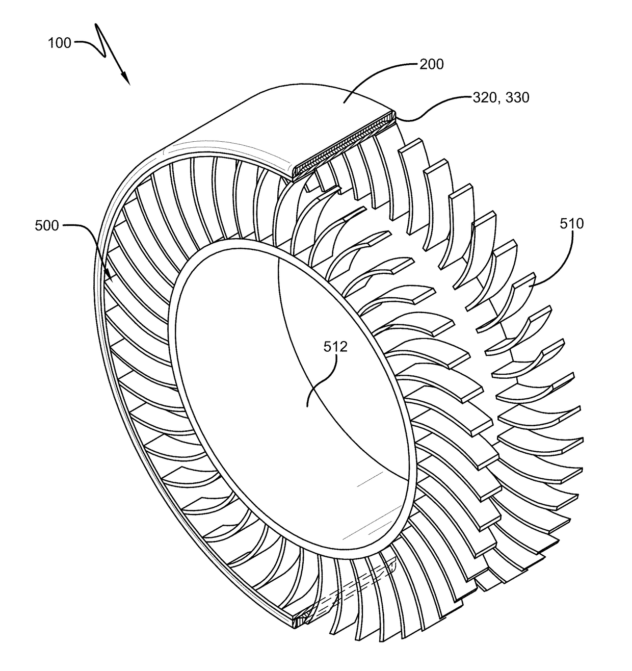
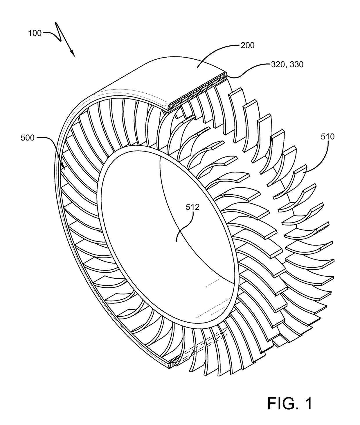
[0032]a non-pneumatic tire 100 of the present invention is shown in FIG. 1. The tire of the present invention includes a radially outer ground engaging tread 200, a shear band 300, and a connecting web 500. The tire tread 200 may include elements such as ribs, blocks, lugs, grooves, and sipes as desired to improve the performance of the tire in various conditions. The connecting web 500 is mounted on hub 512 and may have different designs, as described in more detail, below. The non-pneumatic tire of the present invention is designed to be a top loading structure, so that the shear band 300 and the connecting web 500 efficiently carry the load. The shear band 300 and the connecting web are designed so that the stiffness of the shear band is directly related to the spring rate of the tire. The connecting web is designed to be a stiff structure when in tension that buckles or deforms in the tire footprint and does not compress or carry a compressive load. This allows the rest of the c...

second embodiment

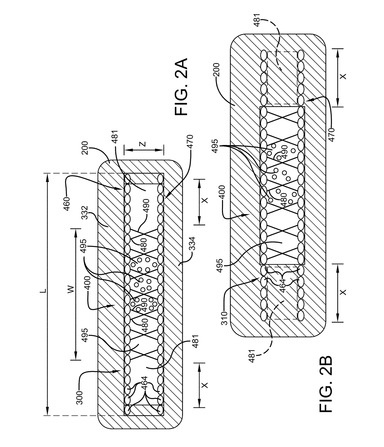
[0036]The three-dimensional fabric structure 400 is preferably oriented in the shear band so that the first and second layers 460,470 are aligned in parallel relation with the axial direction. The three-dimensional fabric structure 400 has a substantial Z dimension thickness which is preferably aligned with the radial direction of the non-pneumatic tire. The open three-dimensional fabric structure 400 thus comprises a plurality of connecting members 480,490 which form open cells 495. As shown in FIG. 2A, one or more of the open cells 495 are filled with a filler material having a desired stiffness. Preferably, two or more open cells 495 are filled with the filler material, and the two or more open cells are located in the axial center of the shear band. The filler material may be an open or closed cell foam, polyurethane foam, EVA, a sealant or other soft material. These foam materials can be made of polyester-terephthalate, polyethylene-terehthalate polyurethane, phenolic foams, po...


PUM

PropertyMeasurementUnit
distanceaaaaaaaaaa
distanceaaaaaaaaaa
distanceaaaaaaaaaa

Abstract

A shear band and a non-pneumatic tire is described which includes a ground contacting annular tread portion; a shear band, and a connecting web positioned between a hub and the shear band. The shear band is preferably comprised of a three-dimensional spacer fabric having a first and second layer connected by connecting members. The three-dimensional spacer fabric has a defined depth. The three-dimensional spacer structure further includes a plurality of cells formed between the connecting members, and wherein one or more of the cells are filled with a filler material. The filler material may be foam or a thermoplastic elastomer.

Description

FIELD OF THE INVENTION[0001]The present invention relates generally to vehicle tires and non-pneumatic tires, and more particularly, to a shear band and non-pneumatic tire.BACKGROUND OF THE INVENTION[0002]The pneumatic tire has been the solution of choice for vehicular mobility for over a century. The pneumatic tire is a tensile structure. The pneumatic tire has at least four characteristics that make the pneumatic tire so dominant today. Pneumatic tires are efficient at carrying loads, because all of the tire structure is involved in carrying the load. Pneumatic tires are also desirable because they have low contact pressure, resulting in lower wear on roads due to the distribution of the load of the vehicle. Pneumatic tires also have low stiffness, which ensures a comfortable ride in a vehicle. The primary drawback to a pneumatic tire is that it requires compressed gasses. A conventional pneumatic tire is rendered useless after a complete loss of inflation pressure.[0003]A tire de...

Claims


Application Information

Patent Timeline
Patent Type & Authority Applications(United States)
IPC IPC(8): B60C7/10
CPCB60C7/105B60C7/102B60C7/00B60C9/1807B32B5/026B32B5/12B60C7/14B60C7/18D03D11/02D10B2403/021D10B2505/022B32B5/022B32B5/024B32B5/06B32B5/08B32B5/10B32B5/18B32B5/26B32B7/12B32B25/10B32B25/12B32B3/08B32B3/12B32B2250/04B32B2250/05B32B2262/0261B32B2262/0269B32B2262/0276B32B2262/10B32B2262/101B32B2262/106B32B2262/14B32B2307/546B32B2307/72B32B2307/732B32B2605/00B60C7/146B60C9/20B60C2009/2012B60C7/107
Inventor SPORTELLI, FRANCESCO
Owner THE GOODYEAR TIRE & RUBBER CO
Why Eureka
Try Eureka