Vehicle body structure

a technology for vehicles and body parts, applied in vehicle components, superstructure sub-units, transportation and packaging, etc., can solve problems such as productivity drop, and achieve the effects of preventing local destruction, reducing stress on side walls and standing walls, and reducing stress on standing walls

Active Publication Date: 2017-10-19
HONDA MOTOR CO LTD
View PDF1 Cites 4 Cited by
  • Summary
  • Abstract
  • Description
  • Claims
  • Application Information

AI Technical Summary

Benefits of technology

[0016]According to the configuration in the first aspect, a metallic joint having a substantially T-shaped cross section configured to join an inner surface in a vehicle width direction of a FRP side wall member extending in a front-rear direction and an outer end in the vehicle width direction of a FRP standing wall member extending in the vehicle width direction includes left-right joining surfaces joined to an inner surface in the vehicle width direction of the side wall member, and a front-rear joining surface which extends inward in the vehicle width direction from an intermediate portion, in the front-rear direction of the left-right joining surfaces and is joined to a front surface or a rear surface of the outer end in the vehicle width direction of the standing wall member. Accordingly, it is possible to rigidly join the side wall member and the standing wall member by increasing the joining area between the side wall member and the standing wall member by the joint. Furthermore, when the collision load due to a side collision is input to the side wall member, the stress of the side wall member and the standing wall member can be alleviated by the deformation of the metallic joint having ductility, and it is possible to prevent the local destruction of the side wall member and the standing wall member.
[0017]According to the configuration in the second aspect, since the positioning pin fitted to the positioning hole formed in the side wall member is provided on the left-right joining surfaces of the joint, it is possible to mutually position and join the side wall member and the joint with high accuracy.
[0018]According to the configuration in the third aspect, the standing wall member is formed in a hollow closed cross section, by superimposing and joining a first joining flange formed by bending the outer end in the vehicle width direction of the first skin main body of the inner skin on the inner side in the front-rear direction inward in the front-rear direction, and a second joining flange formed by bending the outer end in the vehicle width direction of the second skin main body of the outer skin on the outer side in the front-rear direction inward in the front-rear direction, the second skin main body is stuck to the front-rear joining surface of the joint and the second joining flange is stuck to the left-right joining surface of the joint. Accordingly, it is possible to enhance the strength and rigidity by setting the standing wall member to have a hollow closed cross section. Further, the second skin main body and the second joining flange of the outer skin are continuously joined to the front-rear joining surface and the left-right joining surface by the joint to further enhance the joining strength.
[0019]Further, according to the configuration in the fourth aspect, the left-right joining surface of the joint has a first bent portion aligned on the outer side in the vehicle width direction of the second skin main body of the outer skin, and a second bent portion aligned on the outer side in the vehicle width direction of the first skin main body of the inner skin. Accordingly, it is possible to efficiently transmit and disperse the collision load of the side collision from the side wall member to the standing wall member via the joint, while reducing the weight by reducing the thickness of the joint.
[0020]According to the configuration in the fifth aspect, since at least one of the inner skin and the outer skin is formed to be thicker in an outer peripheral portion of the standing wall member than other portions, it is possible to reduce the weight of the standing wall member by the thin central portion, while preventing the destruction of the standing wall member due to stress concentration, by transmitting and dispersing the collision load of the side collision along the thick outer peripheral portion of the standing wall member.
[0021]According to the configuration in the sixth aspect, the standing member includes a core interposed between the inner skin and the outer skin, and the core includes a plurality of grooves extending in the vehicle width direction. Accordingly, it is possible to efficiently support the collision load of the side collision by the standing wall member to enhance absorption effect of the collision energy.

Problems solved by technology

However, in the above-described related art, because the outer end portion of the partition in the vehicle width direction is fitted and stuck into the groove formed between the rear pillar and the rear side member, high component accuracy is required for controlling the groove width, and there is a problem of a decrease in productivity.

Method used


Image

  • Vehicle body structure
  • Vehicle body structure
  • Vehicle body structure

Examples


first embodiment

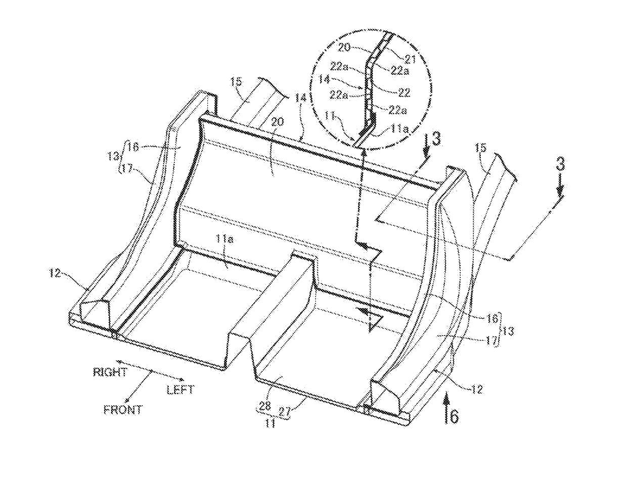
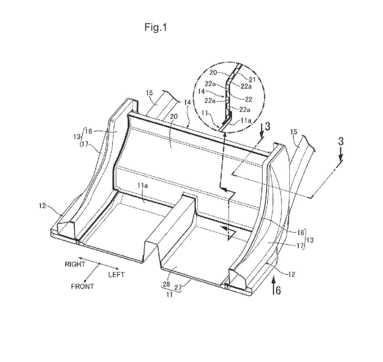
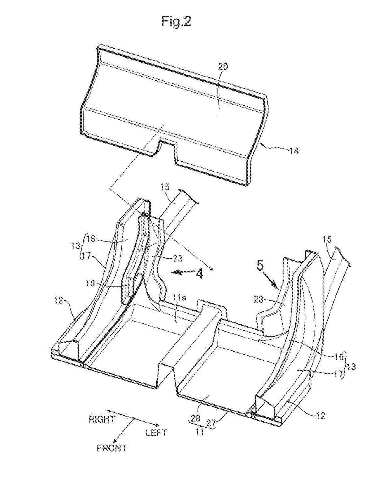
[0032]An embodiment of the present invention will be described below with reference to FIGS. 1 to 7. Further, a front-rear direction, a left-right direction (vehicle width direction) and a vertical direction in this specification are defined on the basis of an occupant seated in a driver's seat.

[0033]As illustrated in FIG. 1, an vehicle body basically made of carbon fiber reinforced resin (CFRP) includes a pair of left and right side sills 12 and 12 extending in the front-rear direction along both left and right side portions of a floor panel 11, and a pair of left and right rear pillars 13 and 13 which stand rearward and upward from the rear ends of the side sills 12 and 12 of the floor panel 11. The left and right side edges of the back panel 14 standing up from the rear end of the floor panel 11 is joined to the inner surface of the left and right rear pillars 13 and 13 in the vehicle width direction. A pair of left and right metal rear side frames 15 and 15 extends rearward from...


PUM


Abstract

A metallic joint 18 having a substantially T-shaped cross section configured to join an inner surface in a vehicle width direction of a FRP side wall member 13 extending in a front-rear direction and an outer end in the vehicle width direction of a FRP standing wall member 14 extending in the vehicle width direction includes left-right joining surfaces 18b and 18c joined to an inner surface in the vehicle width direction of the side wall member 13, and a front-rear joining surface 18a which extends inward in the vehicle width direction from an intermediate portion in the front-rear direction of the left-right joining surfaces 18b and 18c and is joined to a front surface or a rear surface of the outer end in the vehicle width direction of the standing wall member 14.

Description

CROSS-REFERENCE OF RELATED APPLICATION[0001]This application claims priority of Japanese Patent Application No. 2016-080021 filed in Japan on Apr. 13, 2016, the entire contents of which are incorporated herein by reference.TECHNICAL FIELD[0002]The present invention relates to a vehicle body structure in which an inner surface in a vehicle width direction of a FRP (fiber / fiberglass reinforced plastic) side wall member extending in a front-rear direction and an outer end in the vehicle width direction of a FRP standing wall member extending in the vehicle width direction are joined to each other by a metallic joint.BACKGROUND OF THE INVENTION[0003]Japanese patent No. 5056956 described below discloses an vehicle body made of a fiber reinforced resin in which an outer end portion in the vehicle width direction of a partition (back panel) for partitioning a passenger compartment and a rear cargo compartment is fitted into a groove formed between a rear pillar on the front side and a rear...

Claims


Application Information

Patent Timeline
Patent Type & Authority Applications(United States)
IPC IPC(8): B62D29/00B62D25/20B62D25/02
CPCB62D29/005B62D25/2036B62D25/025B62D25/2045B62D29/043
Inventor AYUZAWA, SHOTAROSAKAMOTO, MINORU
Owner HONDA MOTOR CO LTD
Why Eureka
Try Eureka