
Earth electrode apparatus

a technology of earth electrodes and electrodes, which is applied in the direction of resistance electrode holders, electrode features, manufacturing tools, etc., can solve the problems of deformation and wear of earth electrodes, damage to workpieces or earth electrodes b>130/b> locally, and deformation of earth electrodes b>108/b>, so as to avoid heat adhesion of workpieces, simple and compact structure, and stable contact

Active Publication Date: 2012-03-08
SUBARU CORP
View PDF4 Cites 4 Cited by
  • Summary
  • Abstract
  • Description
  • Claims
  • Application Information

AI Technical Summary

Benefits of technology

[0022]The invention is to provide an earth electrode apparatus that does not occupy much space, offers stable contact with a workpiece, and makes it possible to avoid local damage due to melting.

Problems solved by technology

However, the earth electrode 108 is susceptible to deformation and wear.
Moreover, if copper element wires of the earth electrode 108 become damaged, there is a risk that the damaged element wires might melt in contact with the second plate member 102 and become stuck thereto, which degrades the quality of the workpiece.
Therefore, the workpiece or the earth electrode 130 might be damaged locally due to heat generated at the region.

Method used


Image

  • Earth electrode apparatus
  • Earth electrode apparatus
  • Earth electrode apparatus

Examples


first embodiment

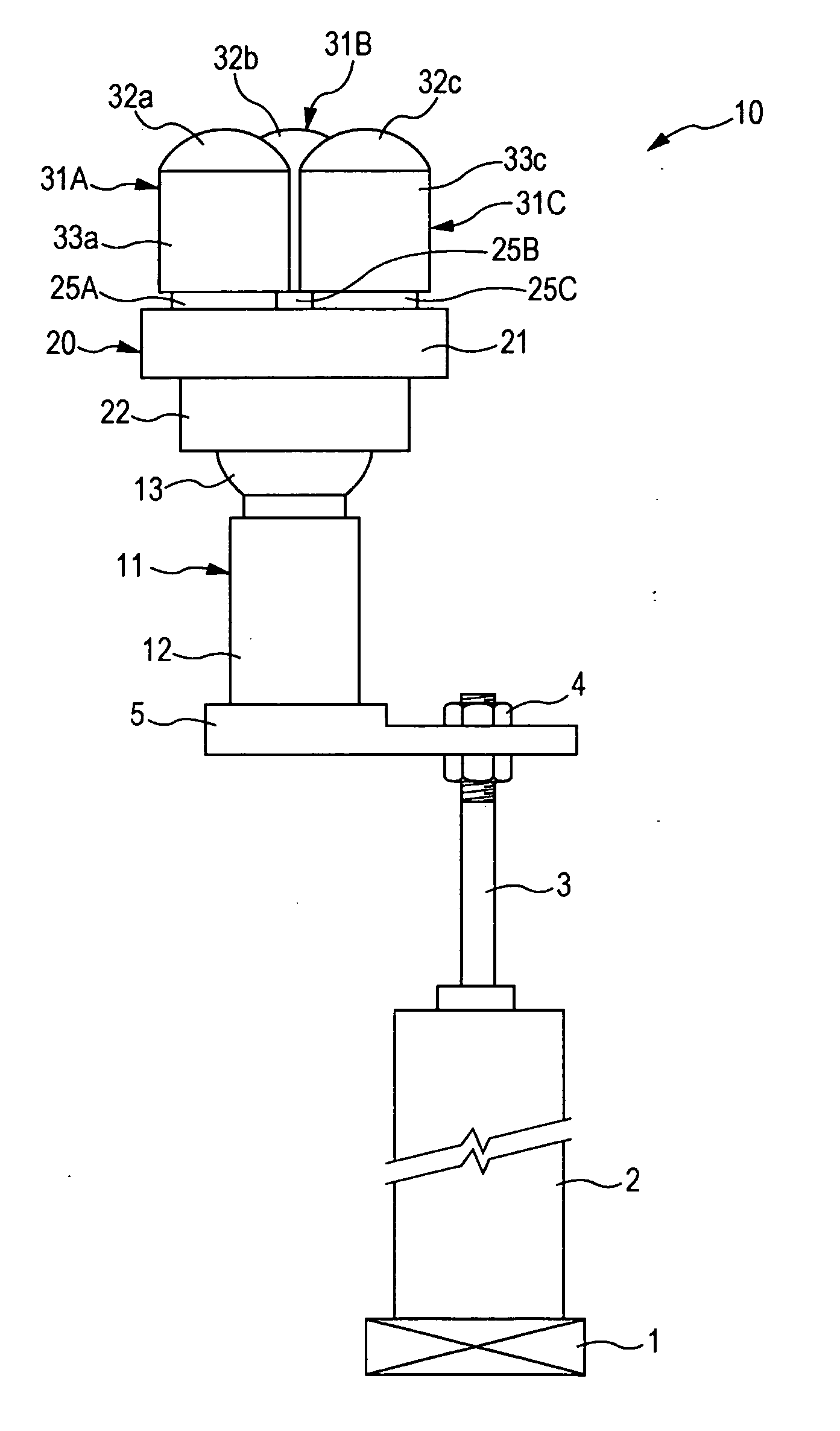
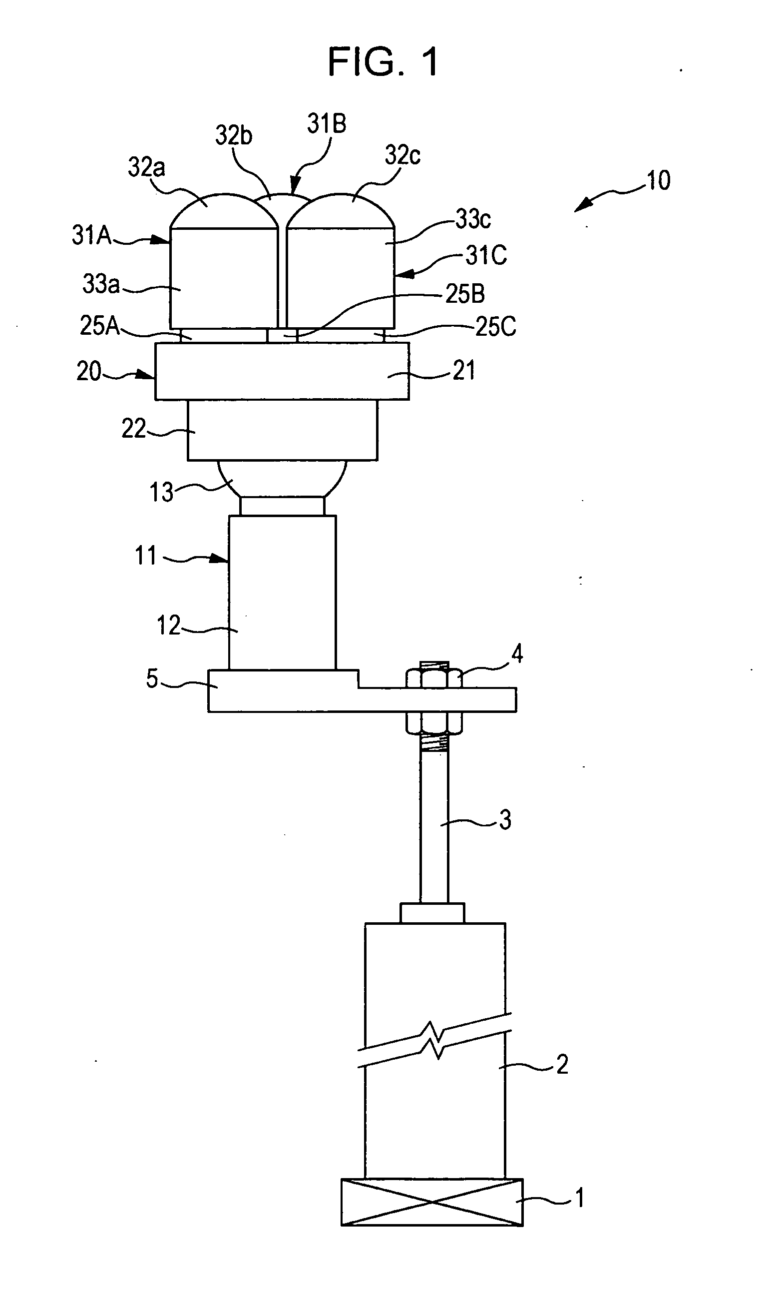
[0057]A first embodiment of the invention will now be explained with reference to FIGS. 1 to 4. FIG. 1 is a diagram illustrating the overall structure of an earth electrode apparatus according to an exemplary embodiment of the invention. An earth electrode assembly 10 is attached to a base 5 that is attached to the tip of a cylinder rod 3 by means of nuts 4. The cylinder rod 3 extends from a cylinder unit 2 attached to a robot arm 1.

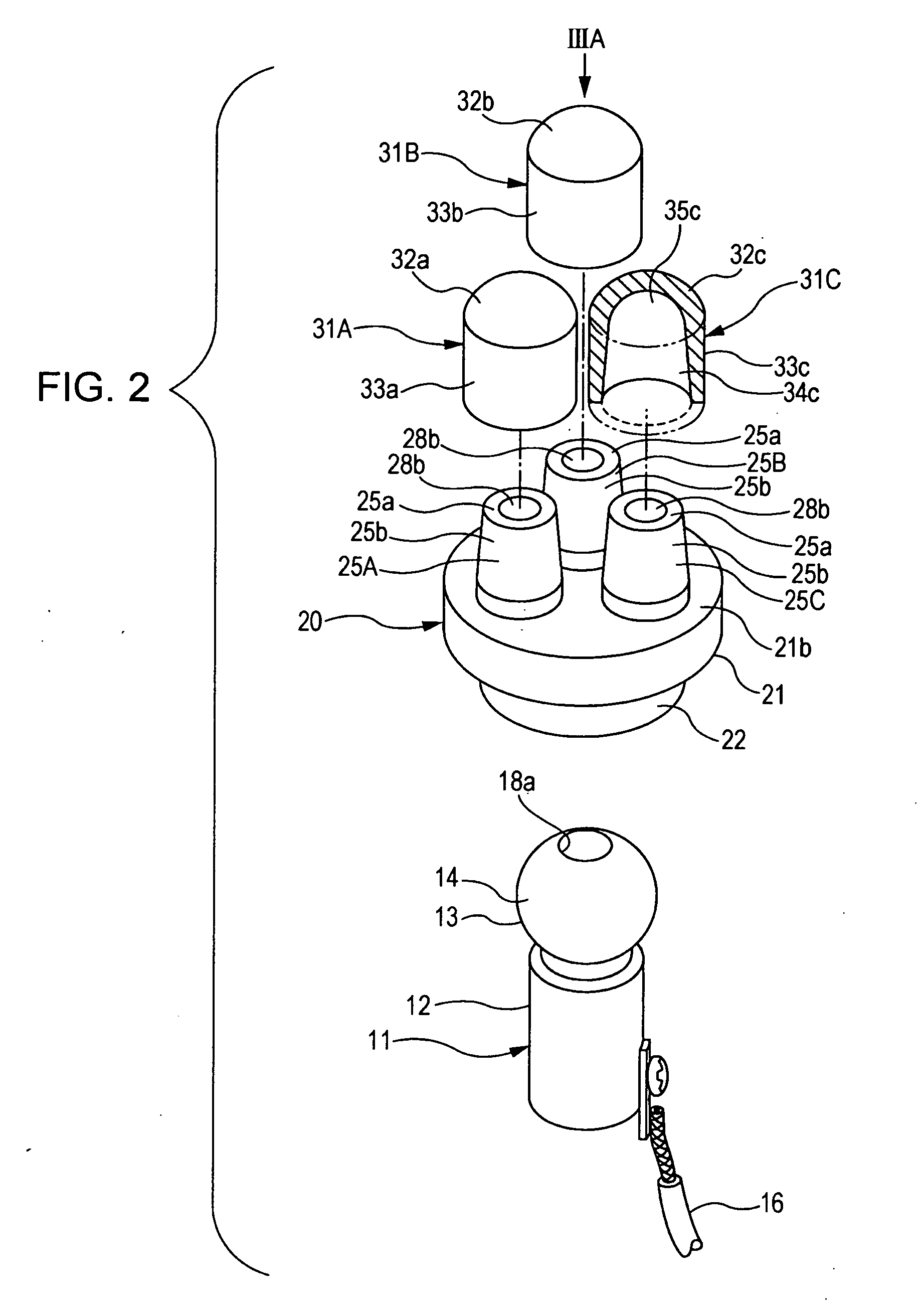
[0058]The earth electrode apparatus 10 includes a shaft 11, a cradle 20, a first earth electrode 31A, a second earth electrode 31B, and a third earth electrode 31C. The shaft 11 is attached to the base 5 in an electrically insulated state. The cradle 20 is coupled to the shaft 11 as a freely tiltable member. The first earth electrode 31A, the second earth electrode 31B, and the third earth electrode 31C are detachably attached to a first shank 25A, a second shank 25B, and a third shank 25C that are formed on the cradle 20, respectively.

[0059]FIG. 2 is an...

second embodiment

[0095]A second embodiment of the invention will now be explained with reference to FIGS. 5 to 8. FIG. 5 is a diagram illustrating the overall structure of an earth electrode apparatus 50. FIG. 6A is a fragmentary view corresponding to FIG. 5. The view is taken in the direction of an arrow VIA illustrated therein. FIG. 6B is a sectional view taken along the line VIB-VIB of FIG. 5A.

[0096]The earth electrode assembly 50 is attached to the base 5, which is attached to the tip of a cylinder rod extending from a cylinder unit attached to a robot arm as in the structure according to the first embodiment of the invention.

[0097]The earth electrode apparatus 50 includes an attachment pedestal 51, a fixed shaft 61, a tiltable shaft member 70, a cradle 80, a first earth electrode 91A, a second earth electrode 91B, and a third earth electrode 91C. The attachment pedestal 51 is attached to the base 5 in an electrically insulated state. The shaft 61 is fixed to the attachment pedestal 51. The shaf...


PUM

PropertyMeasurementUnit
currentaaaaaaaaaa
conductiveaaaaaaaaaa
cylindrical shapeaaaaaaaaaa

Abstract

In an earth electrode apparatus, a cradle having first, second, and third shanks to which first, second, and third earth electrodes can be attached respectively is coupled to a shaft supported by a base. The cradle is coupled thereto in a tiltable manner. If the surface of a workpiece is irregular or inclined, the cradle tilts for balancing with the workpiece to ensure equal contact pressure for the contact of the first, second, and third earth electrodes with the workpiece, thereby offering stable contact irrespective of surface irregularity or inclination. Since a welding current is split to flow into the first, second, and third earth electrodes through respective points of contact thereof with the workpiece, it is possible to reduce current density at each of the points of contact and to avoid heat generation ascribable to conductive resistance at each of the points of contact.

Description

CROSS-REFERENCE TO RELATED APPLICATIONS[0001]The present application claims priority from Japanese Patent Application No. 2010-200664 filed on Sep. 8, 2010 and Japanese Patent Application No. 2011-065358 filed on Mar. 24, 2011, the entire contents of which are hereby incorporated by reference.BACKGROUND OF THE INVENTION[0002]1. Field of the Invention[0003]The present invention relates to an earth electrode apparatus and, more particularly, to an earth electrode apparatus for conductive contact of an earth electrode with a workpiece.[0004]2. Description of the Related Art[0005]In related art, direct spot welding or series welding is used for the welding of a workpiece made up of plate members laid one on top of the other. A large electric current is applied for a certain period to the workpiece sandwiched between a pair of weld electrodes while applying welding pressure thereto. A nugget is formed due to heat generated at a weld region, thereby welding the plate members together.[000...

Claims


Application Information

Patent Timeline
Patent Type & Authority Applications(United States)
IPC IPC(8): B23K11/30B23K11/31
CPCB23K11/3009B23K11/11
Inventor SAKAI, KENSUKE
Owner SUBARU CORP
Learn More