Antenna system and control method

a technology of antenna system and control method, applied in the field of smart antenna, can solve the problems of interference between the radiation pattern of the antenna and the other, and achieve the effects of improving user experience, accurate locating mechanism, and optimal data transmission ra

Active Publication Date: 2017-10-19
PEGATRON
View PDF2 Cites 3 Cited by
  • Summary
  • Abstract
  • Description
  • Claims
  • Application Information

AI Technical Summary

Benefits of technology

[0008]According to the technology disclosed here, the antenna system can have the function of selectively adjusting the pointing direction of antenna radiation pattern and have more accurate locating mechanism, so an optimal data transmission rate can be achieved. Accordingly, a user can have an improved user experience.

Problems solved by technology

When multiple antennas are disposed in array, the radiation patterns of them may interfere with each other.

Method used


Image

  • Antenna system and control method
  • Antenna system and control method
  • Antenna system and control method

Examples


Embodiment Construction

[0018]Specific embodiments of the present invention are further described in detail below with reference to the accompanying drawings, however, the embodiments described are not intended to limit the present invention and it is not intended for the description of operation to limit the order of implementation. Moreover, any device with equivalent functions that is produced from a structure formed by a recombination of elements shall fall within the scope of the present invention. Additionally, the drawings are only illustrative and are not drawn to actual size. In accordance with the standard practice in the industry, various features are not drawn to scale. In fact, the dimensions of the various features may be arbitrarily increased or reduced for clarity of discussion.

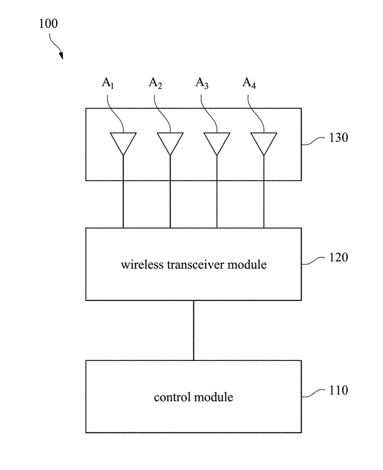
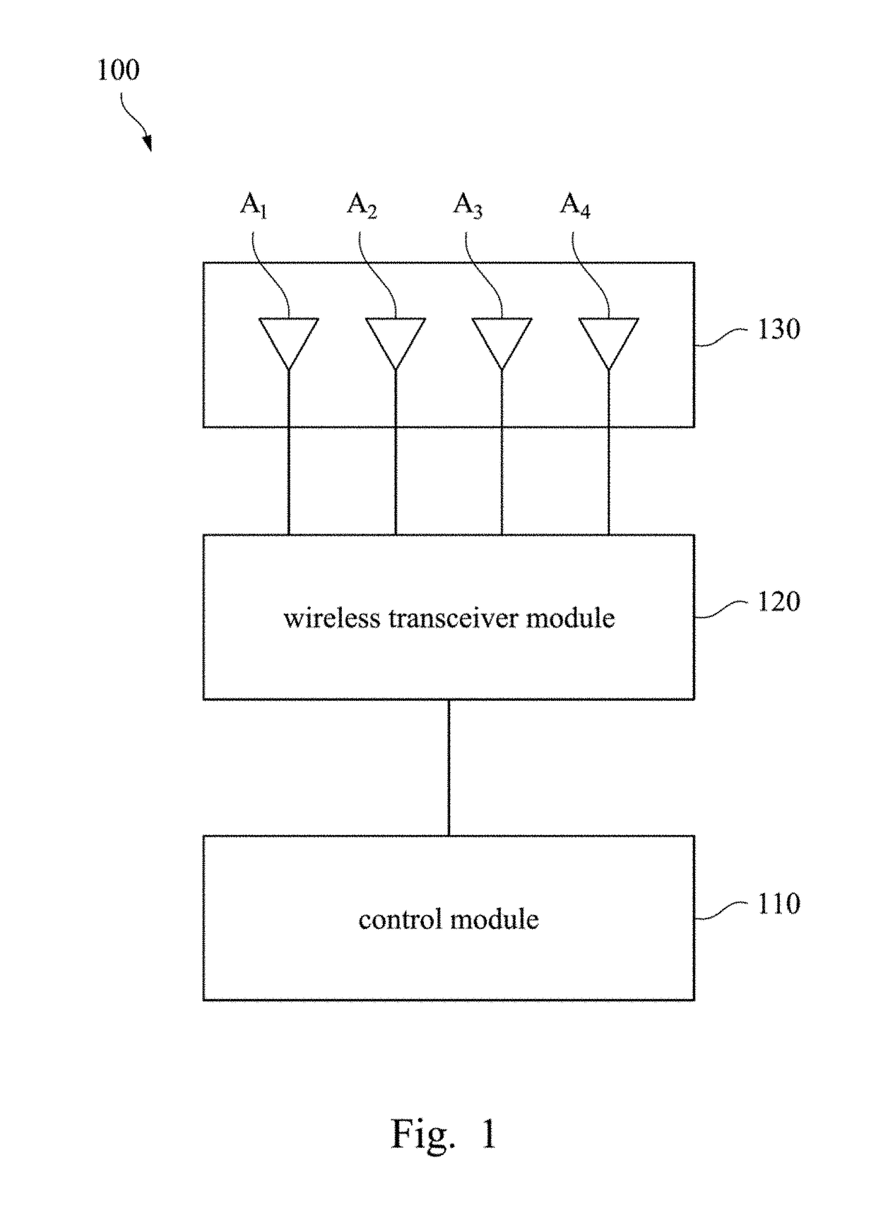
[0019]Reference is made first to FIG. 1. FIG. 1 depicts a block diagram of an antenna system 100 according to an embodiment of this disclosure. As shown in FIG. 1, the antenna system 100 includes a control module 110...


PUM


Abstract

An antenna system includes an antenna array, a wireless transceiver module and a control module. The antenna array includes a first antenna and a second antenna coupled respectively to the wireless transceiver module. The wireless transceiver module sends and receives signals via the first antenna based on a first phase and sends and receives signals via the second antenna based on a second phase. The control module coupled to the wireless transceiver module, and controls the phase difference between the first phase and the second phase. The radiation pattern of the antenna array is modulated towards one pointing direction based on the phase difference.

Description

RELATED APPLICATIONS[0001]This application claims priority to Taiwan Application Serial Number 105111887, filed Apr. 15, 2016, which is herein incorporated by reference.BACKGROUNDTechnical Field[0002]The present disclosure relates to an antenna system. More particularly, the present disclosure relates to a smart antenna, system which can change phase.Description of Related Art[0003]Modern communication technology is flourishing and has become an indispensable part of modern life. As quality of life improves, faster transmission rates and better signal receiving quality of communication for electronic devices is in demand,[0004]Most traditional wireless area network or bridge antennas using 802:11at / gin protocol have an exposed dipole antenna structure such as multi-input multi-output (MIMO) antenna module having multiple loops, which has Wi-Fi 2.4G antennas and Wi-Fi 5G antennas disposed alternately. One of the common antenna radiation patterns is omnidirectional. When multiple ante...

Claims


Application Information

Patent Timeline
Patent Type & Authority Applications(United States)
IPC IPC(8): H01Q3/34H01Q21/24
CPCH01Q21/245H01Q3/34H01Q1/2291H01Q3/30H01Q21/065
Inventor WU, CHIEN-YILI, YA-JYUNWU, CHAO-HSUYU, HUNG-MINGLEE, I-SHU
Owner PEGATRON
Why Eureka
Try Eureka