Connector module

a technology of connecting modules and connectors, applied in the direction of fixed connections, modification by conduction heat transfer, coupling device connections, etc., can solve the problems of adversely affecting the data transmission rate and poor heat dissipation efficiency of current connector modules, and achieve good data transmission rate and improved heat dissipation efficiency

Active Publication Date: 2015-09-15
ALL BEST PRECISION TECH
View PDF5 Cites 18 Cited by
  • Summary
  • Abstract
  • Description
  • Claims
  • Application Information

AI Technical Summary

Benefits of technology

[0012]With the above arrangements, the connector module of the present invention can have improved heat dissipation efficiency to ensure good data transmission rate.

Problems solved by technology

However, most of the current connector modules have poor heat dissipation efficiency to adversely affect the data transmission rate because the heat produced by the connector modules during operation thereof is dissipated only by convection.

Method used


Image

  • Connector module
  • Connector module
  • Connector module

Examples


first embodiment

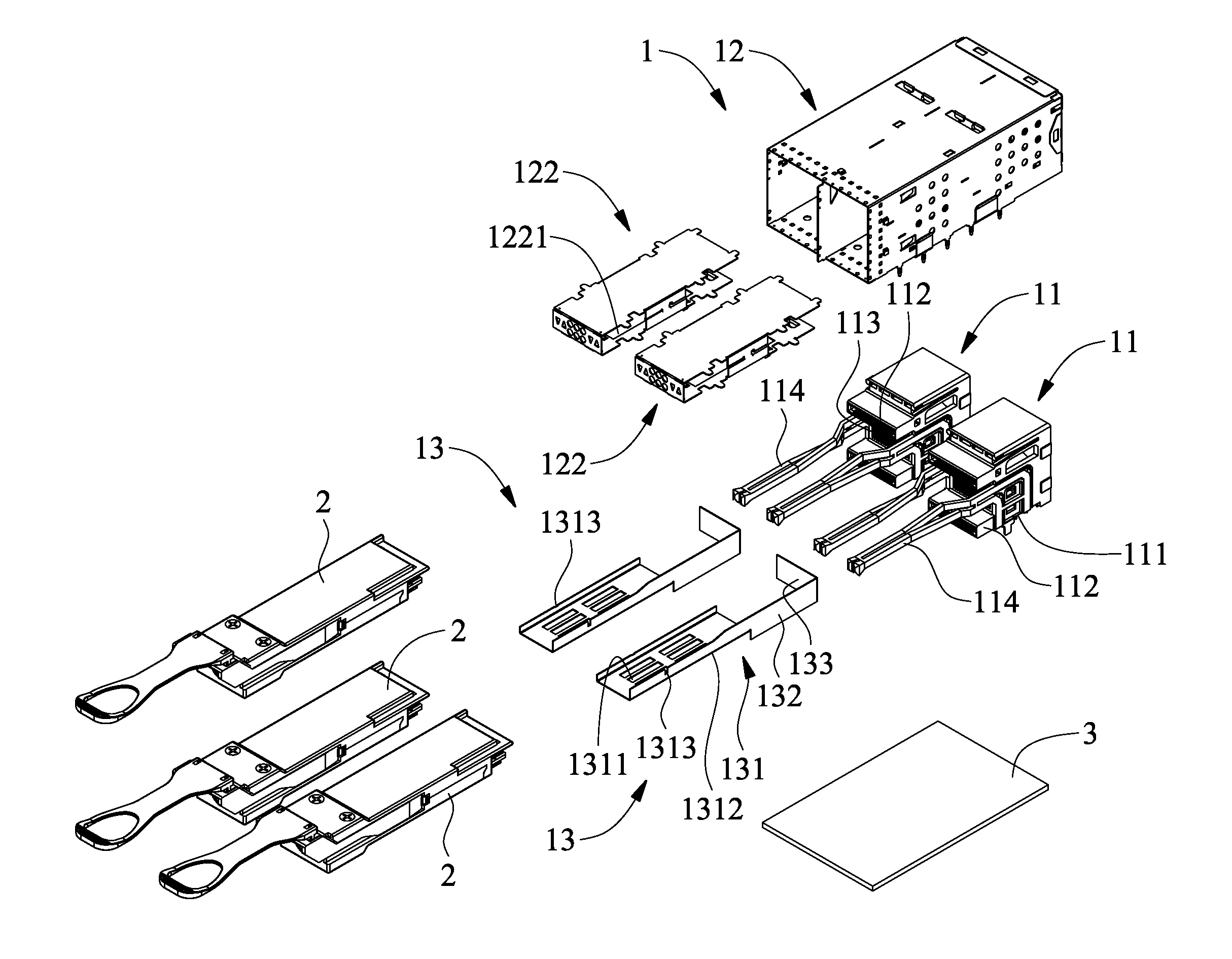
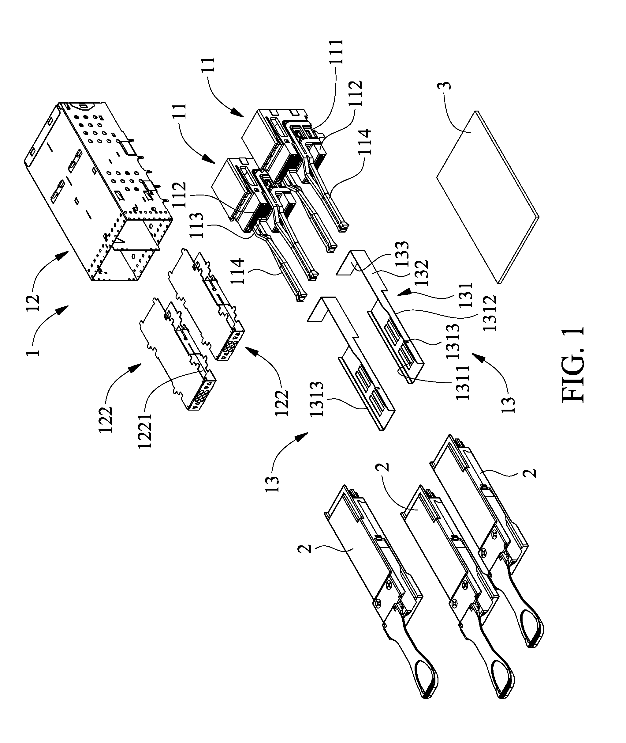
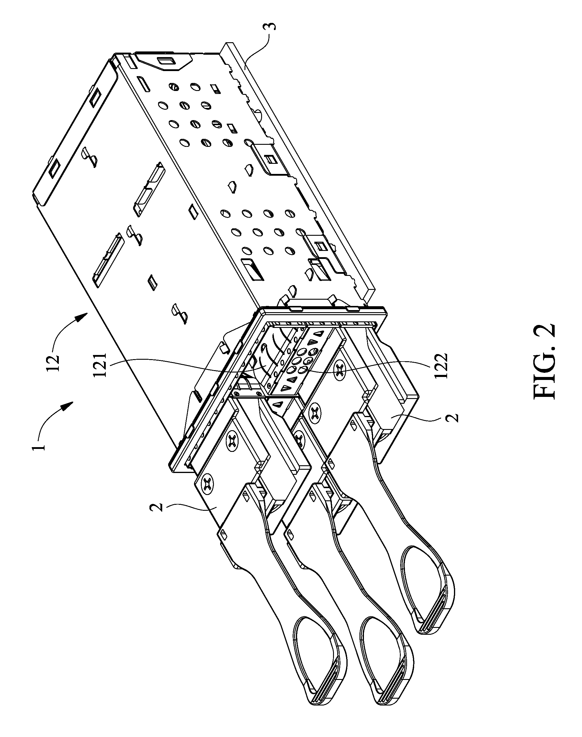
[0032]According to the connector module in the present invention, waste heat produced by the connector module main body 1 and the plug devices 2 can be transferred by the heat-dissipation element 13 to finally dissipate into an outer side of the connector module by way of convection. With these arrangements, both the connector module main body 1 and the plug devices 2 can have upgraded heat dissipation efficiency and data transmission rate. In the case the connector module main body 1 includes both the heat-dissipation passages 1131 and the heat outlets 123, an even better heat dissipation effect can be obtained for the connector module main body 1 through heat transfer and convection.

[0033]Please refer to FIGS. 1 to 6. In the first embodiment of the connector module, the heat-dissipation element 13 includes three sequentially arranged sections, namely, a heat-absorption section 131, a heat-transfer section 132, and a heat-dissipation section 133. In an assembled state of the connec...

third embodiment

[0038]As can be seen in FIG. 8, the heat-absorption unit 141 can be a heat-absorbing sheet and the heat-dissipation unit 142 can be a radiation fin. In the embodiment shown in FIG. 8, the heat-dissipation unit 142 can be welded or glued to the top of the heat-absorption unit 141. In the present invention as shown in FIG. 16, the heat-absorption unit 141 and the heat-dissipation unit 142 can be integrally formed by cutting and bending a substantially T-shaped flat sheet.

[0039]Please refer to FIGS. 15 and 16. In the second and the third embodiment, the heat-absorption unit 141 can be stamped or be cut and bent to form at least one downward protruded portion 1411. In this case, the heat-absorbing surface 1412 is located on the at least one protruded portion 1411. When the lower plug device 2 passes through the lower slot way 121, the heat-absorbing surface 1412 on the at least one protruded portion 1411 is in direct contact with part of the top outer surface of the lower plug device 2 ...


PUM


Abstract

A connector module includes a connector module main body having a base and a case, and a heat-dissipation element. The base has an external connection surface and two top-and-bottom spaced slots located above the external connection surface. The case internally defines an upper and a lower slot way separated from each other by a supporting rack, which has a bottom opening. The base is fitted in the case with the external connection surface downward exposed from the case and the two slots communicating with the upper and lower slot ways. The heat-dissipation element is mounted in the connector module main body in a front-rear direction with a heat-absorbing surface located corresponding to the bottom opening of the supporting rack and above the lower slot way for contacting with a plug device in the lower slot way to ensure good heat-dissipation efficiency and data transmission rate of the connector module.

Description

FIELD OF THE INVENTION[0001]The present invention relates to a connector module, and more particularly, to a connector module that has improved heat-dissipation efficiency and data transmission rate.BACKGROUND OF THE INVENTION[0002]Presently, various kinds of electronic apparatuses are constantly developed, and these electronic apparatuses all need connector modules to enable data transmission among them. However, most of the current connector modules have poor heat dissipation efficiency to adversely affect the data transmission rate because the heat produced by the connector modules during operation thereof is dissipated only by convection. Therefore, it is tried by the inventor to develop a connector module that has improved heat dissipation efficiency to ensure good data transmission rate.SUMMARY OF THE INVENTION[0003]To overcome the drawbacks of the conventional connector modules, it is a primary object of the present invention to provide a new connector module that has improve...

Claims


Application Information

Patent Timeline
Patent Type & Authority Patents(United States)
IPC IPC(8): H01R13/00H01R13/46H05K7/20H01R12/50
CPCH05K7/2039H01R13/46H01R23/7073H01R12/724H01R13/518H01R12/00
Inventor YANG, HAVEN
Owner ALL BEST PRECISION TECH
Why Eureka
Try Eureka